
Adaptive threshold control circuit and method within high speed receivers

Inactive Publication Date: 2001-08-14
AVAGO TECH INT SALES PTE LTD
View PDF4 Cites 47 Cited by
  • Summary
  • Abstract
  • Description
  • Claims
  • Application Information

AI Technical Summary

Problems solved by technology

The situation is different, however, when the noise is asymmetrical.
With the advent of wavelength division multiplexing (WDM) systems, however, the problem has become much more severe.
A one-time adjustment in this case is inadequate.
One drawback of the above methods is that, since a minimum in the bit error ratio must be found, a search algorithm must be used, which requires a microprocessor controlled monitoring system running a complex program.
Furthermore, the methods are not very adaptive since a change in BER can mean two things: either the minimum BER or the optimum threshold has changed.
Hence, in the above cases, an ambiguity results when a change in BER is detected.
This ambiguity in V.sub.OPT tends to reduce the overall receiver sensitivity.

Method used


Image

  • Adaptive threshold control circuit and method within high speed receivers
  • Adaptive threshold control circuit and method within high speed receivers
  • Adaptive threshold control circuit and method within high speed receivers

Examples


Embodiment Construction

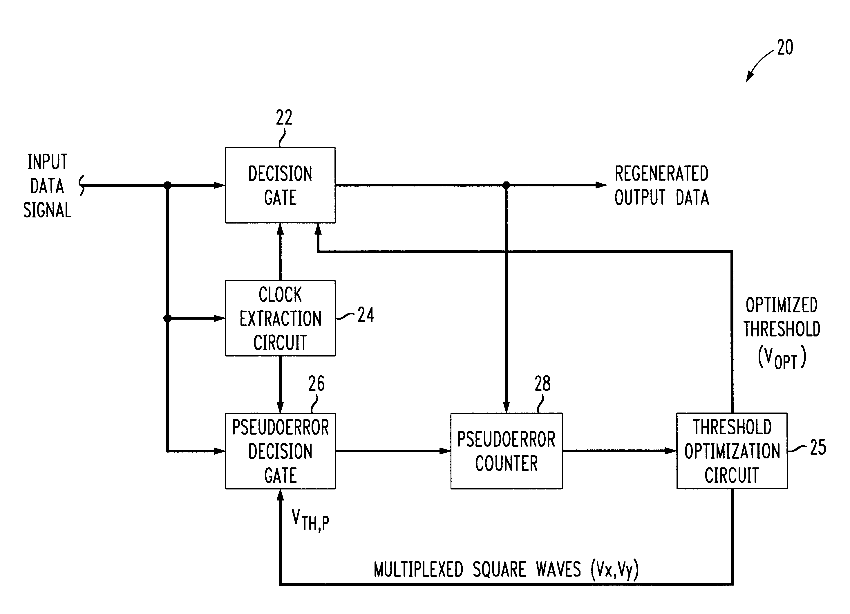
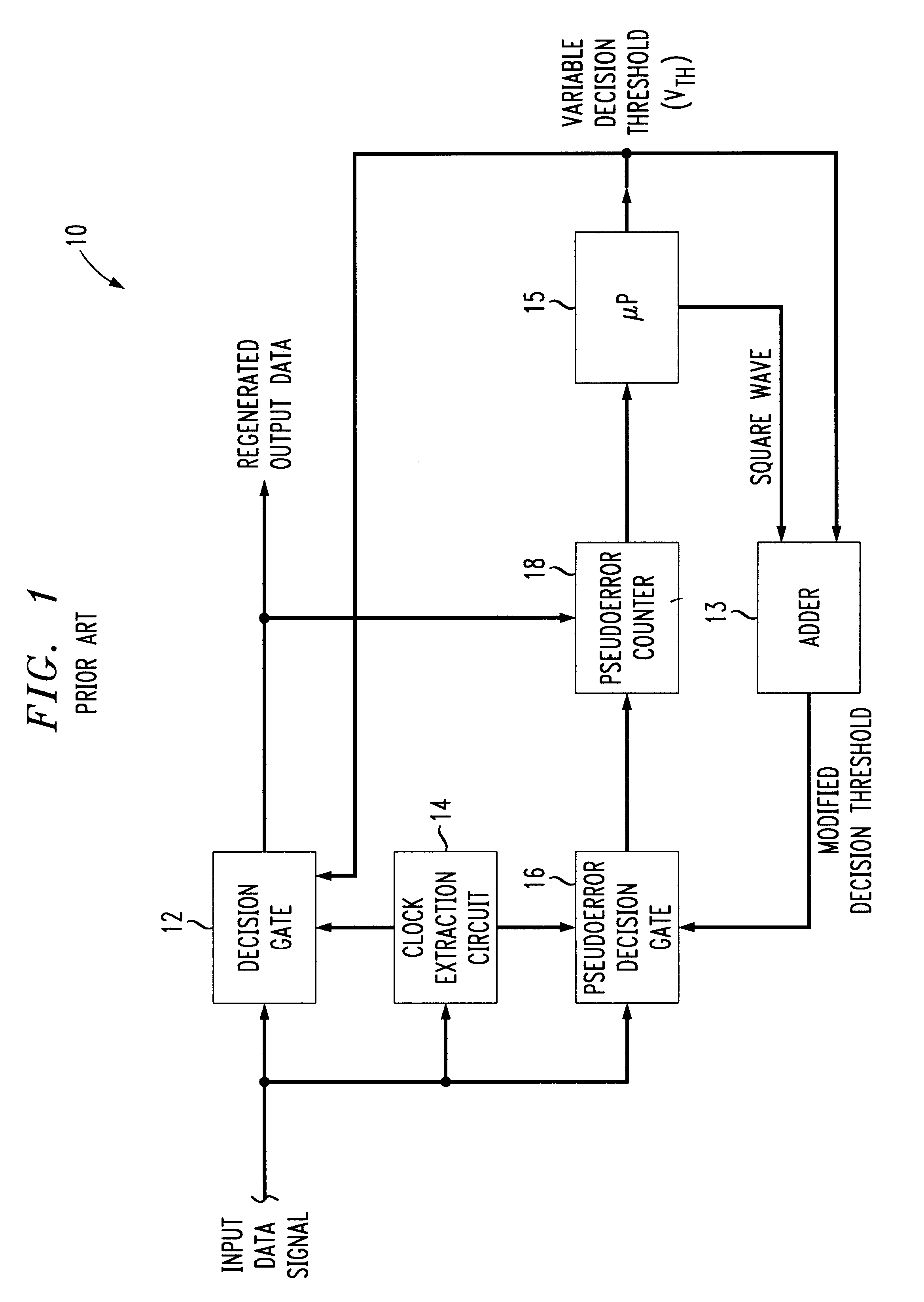
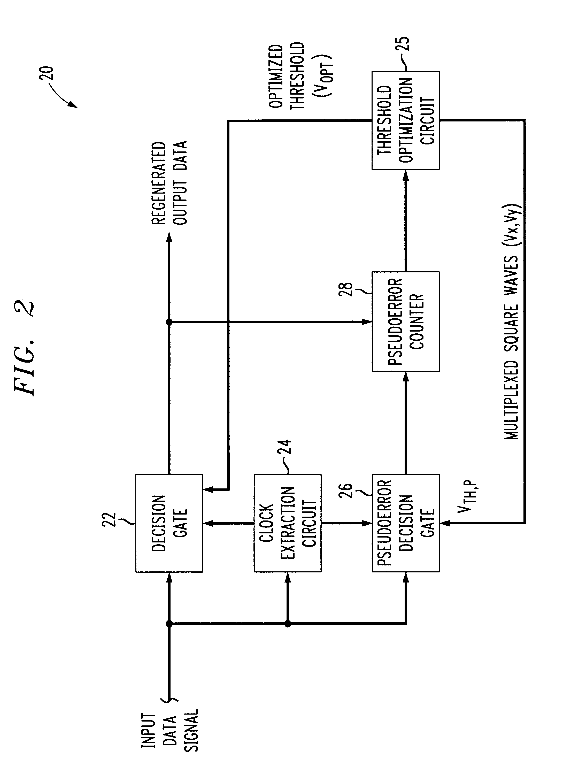
Referring to FIG. 2, an embodiment of a data regeneration circuit, 20, in accordance with the invention is illustrated in block diagram form. As in the prior art circuit of FIG. 1, an input data signal (herein referred to interchangeably as a "symbol stream") is amplified and then applied to each of a main decision gate 22, clock extraction circuit 24 and pseudoerror decision gate 26. Pseudoerror counter 28 compares the logic level outputs of decision gates 22 and 26 and increments a count whenever a difference is detected, i.e., whenever one of the decision gate outputs is logic zero while the other is logic one.

In contrast to the previous methods, regeneration circuit 20 does not apply a sweeping decision threshold voltage superimposed with a square wave to the pseudoerror gate 26 and then search for a minimum PBER. Instead, a threshold optimization circuit 25 generates a decision threshold signal V.sub.TH,P comprised of two multiplexed square waves V.sub.X, V.sub.Y for applicatio...


PUM


Abstract

Disclosed is a data regeneration circuit including a decision gate for regenerating a symbol stream (e.g., bit stream) by comparing the amplitude of individual symbols thereof to a decision threshold and outputting a logic level in accordance with each comparison. Threshold optimization circuitry dynamically measures first and second probability distribution points of each symbol, and based on the measurements, optimizes the decision threshold applied to the decision gate. A parallel pseudoerror path including a pseudoerror decision gate and pseudoerror counter may be employed to facilitate the measurements.

Description

The present invention pertains generally to data regeneration within high speed optical receivers and the like.An optical receiver typically includes an optical detector for detecting an incoming optical signal (e.g., bit stream), a linear preamplifier and a decision circuit. The bit stream is comprised of logic zero and logic one data bits transmitted at different signal levels, i.e., "zero" and "one" levels. The decision circuit samples the detected bit stream and determines whether each bit is a one or a zero by comparing its detected signal level to a decision threshold in between the expected zero and one levels. A given sample is assumed to be a logic one if it exceeds the threshold, or logic zero otherwise. In receivers with dynamic adjustment capability, as the optical signal is received, the bit error ratio (BER) of the receiver is measured and the decision threshold is continually adjusted to minimize the BER.When the amount of uncertainty, or noise, on both one and zero l...

Claims


Application Information

Patent Timeline
IPC IPC(8): H04L1/20H04L25/06
CPCH04L25/061H04L1/205
Inventor RANSIJN, JOHANNES GERARDUS
Owner AVAGO TECH INT SALES PTE LTD
Learn More