Variable capacity refrigerant compressor having an inclination limiting means to interrupt compressive forces on a hinge mechanism

a variable capacity, compressor technology, applied in the direction of positive displacement liquid engine, positive displacement engine, reciprocating piston engine, etc., can solve the problems of deteriorating the controllability of the displacement capacity of the compressor, the delay in altering the angle of inclination of the cam, etc., to reduce the load proportion and reduce the weight of the cam plate

Inactive Publication Date: 2001-08-21
TOYOTA IND CORP
View PDF8 Cites 8 Cited by
  • Summary
  • Abstract
  • Description
  • Claims
  • Application Information

AI Technical Summary

Benefits of technology

to provide variable displacement compressors which makes it possible to lower the proportion of load supported by a hinge mechanism to a maximum ...

Problems solved by technology

A major problem resulting from such increase in the weight of the cam plate 104 in the conventional structure has been the delay in al...

Method used


Image

  • Variable capacity refrigerant compressor having an inclination limiting means to interrupt compressive forces on a hinge mechanism
  • Variable capacity refrigerant compressor having an inclination limiting means to interrupt compressive forces on a hinge mechanism
  • Variable capacity refrigerant compressor having an inclination limiting means to interrupt compressive forces on a hinge mechanism

Examples


first embodiment

The first embodiment described hereinbefore provides the following advantageous effects:

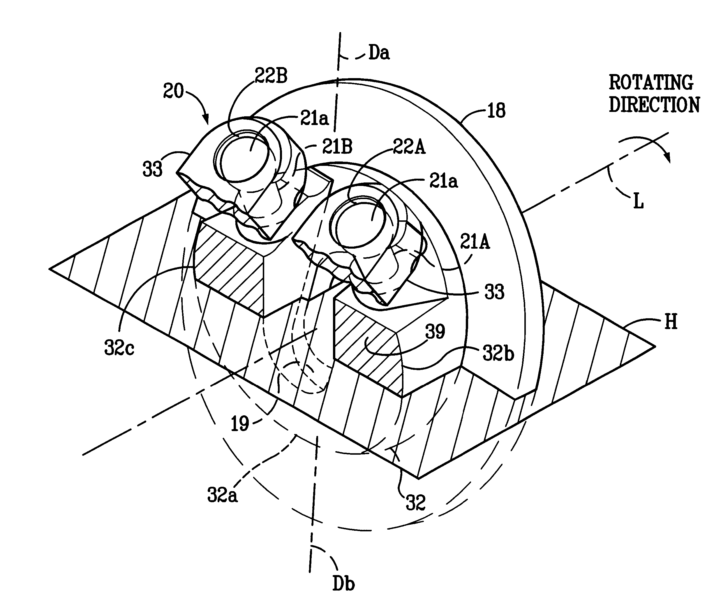
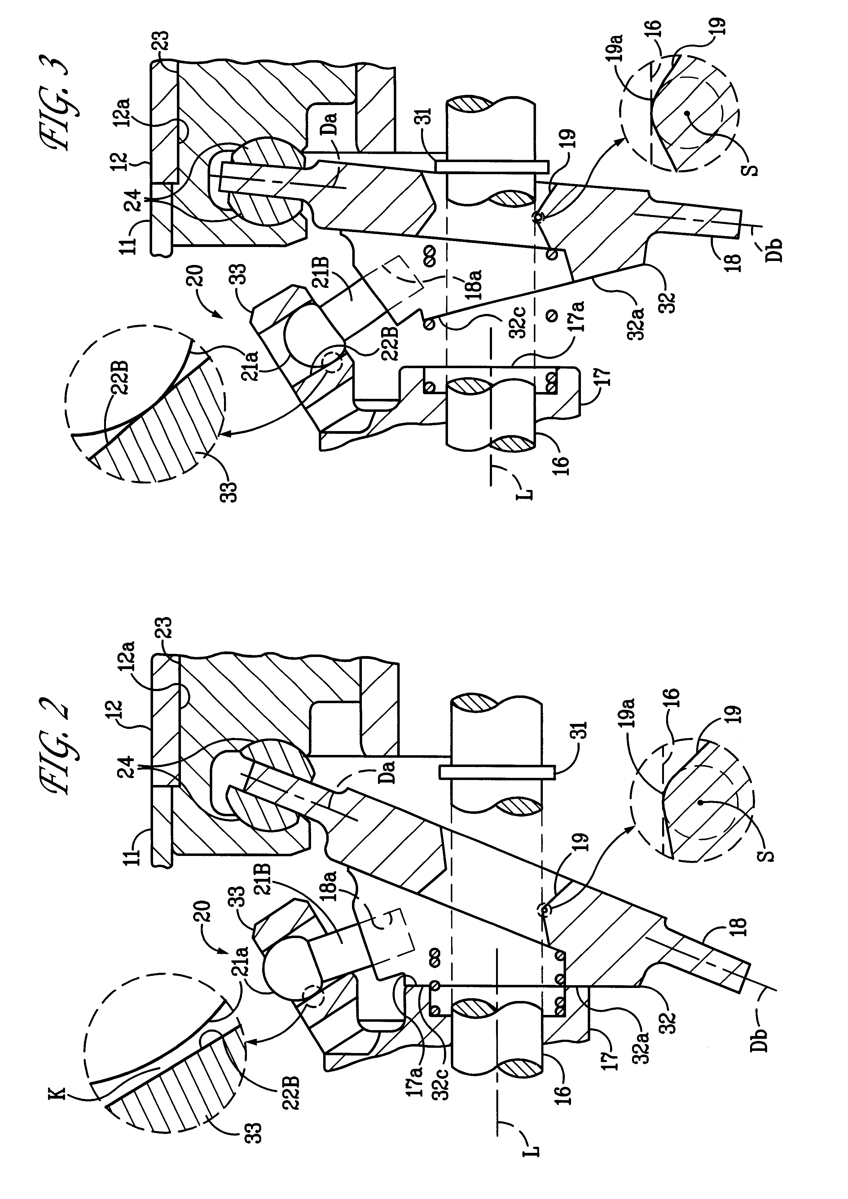
(1) A pair of guide pins 21A, 21B are provided on both sides of the point Da of the cam plate 18 corresponding to the top dead center. The area of contact between the bulbous part 21a of the guide pin 21A and the guide hole 22A, which are closer to the piston 23 in a compression stroke, shares a greater proportion of the compressive load than the area of contact between the bulbous part 21a of the guide pin 21B and the guide hole 22B. However, when the cam plate 18 is in its maximum angle of inclination, there is formed the clearance K between the bulbous part 21a of the guide pin 21A and the guide hole 22A so that transmission of the compressive load between the guide pin 21A and the guide hole 22A is interrupted. It is therefore possible to significantly reduce the proportion of load to be supported by the hinge mechanism 20 to the maximum compressive load applied to the cam plate 18 when the c...

second embodiment

FIGS. 6 to 8 depict a second embodiment of the invention employing a hinge mechanism 40 whose construction is somewhat different from the hinge mechanism 20 of the first embodiment. Specifically, the hinge mechanism 40 includes a swing arm 41 projecting from a cam plate 18 at its point Da corresponding to a top dead center. The swing arm 41 extends toward a rotary support 17 and a fixing hole 41 a is formed in a far end portion of the swing arm 41 at right angles to an axis L of a drive shaft 16. A guide pin 42 is securely press-fitted in the fixing hole 41a. Both terminal portions 42a, 42b of the guide pin 42 which serve as guiding projections jut out from both sides of the swing arm 41 along the rotating direction of the drive shaft 16.

There are provided a pair of supporting arms 43A, 43B on the rotary support 17 projecting from an outer peripheral part of its rear surface on both sides of the point Da of the cam plate 18 corresponding to the top dead center, one ahead of and the ...


PUM


Abstract

A maximum inclination setting projection comes into contact with a rotary support in a region closer to a point corresponding to a top dead center than an imaginary two-part dividing plane, thereby establishing a maximum angle of inclination of a cam plate. Thus, a hinge mechanism is not required to support any proportion of a compressive load in the region closer to the point corresponding to the top dead center than the imaginary two-part dividing plane when the cam plate is in its maximum angle of inclination. Bulbous parts of guide pins do not come in contact with halves of cylindrical inside surfaces of guide holes closer to the rotary support, and there is made a clearance between the bulbous part of the guide pin and the guide hole and between the bulbous part of the guide pin and the guide hole, interrupting transmission of the compressive load between them.

Description

1. Field of the InventionThe present invention relates to variable displacement compressors which are employed in motor vehicle air-conditioning systems, for instance.2. Description of the Related ArtFIG. 10 shows a conventionally known structure employed in a variable displacement compressor of this kind, in which cylinder bores 101a are formed in a housing 101, a drive shaft 102 is rotatably supported in the housing 101, a rotary support 103 is fixed to the drive shaft 102, a cam plate 104 is supported by the drive shaft 102 which is passed through a through hole 104a formed in the cam plate 104, and pistons 105 fitted in the individual cylinder bores 101a are joined to the cam plate 104. A maximum inclination setting projection 106 protrudes from about a point Db of the cam plate 104 corresponding to a bottom dead center toward the rotary support 103.A hinge mechanism 107 comprises guide pins 108 provided close to a point Da of the cam plate 104 corresponding to a top dead center...

Claims


Application Information

Patent Timeline
IPC IPC(8): F04B27/10F04B27/08
CPCF04B27/1072
Inventor OTA, MASAKIKURITA, HAJIMENISHIMURA, KENTAKURAKAKE, HIROTAKA
Owner TOYOTA IND CORP
Why Eureka
Try Eureka