
Method of retrofitting a furnace to provide oxygen enrichment

a technology of retrofitting and enrichment furnace, which is applied in the direction of indirect carbon-dioxide mitigation, combustion using lump and gaseous fuel, combustion using liquid fuel, etc., can solve the problems of insufficient oxygen supply, insufficient oxygen supply, and insufficient oxygen supply, and achieve the effect of reducing the number of regenerative furnaces

Inactive Publication Date: 2001-08-21
AIR LIQUIDE AMERICA INC
View PDF16 Cites 94 Cited by
  • Summary
  • Abstract
  • Description
  • Claims
  • Application Information

AI Technical Summary

Problems solved by technology

Thermal efficiency of the regenerative furnaces may suffer due to an insufficient oxygen supply from a variety of causes.
Insufficient oxygen supply may be caused by regenerator plugging, cracks in the regenerator, or other regenerator failure.
However these solutions to insufficient oxygen supply all have substantial drawbacks.
For example, it is often difficult to install additional oxygen lances or oxy-fuel burners in the furnace due to design or space constraints.
The spaces where burners or lances can be placed are defined by burner geometry and improper placement can lead to quality problems, crown overheating, or regenerator hot spots that can dramatically reduce the useful life of the furnace.
Often there is insufficient space for drilling holes for installation of the additional lances or burners at the desired locations beside or below the firing ports.
In addition, refractory core drilling or refractory block removal to allow installation of the additional lances or burners can be physically impossible or at least very costly.
Global oxygen enrichment to improve efficiency is not an efficient solution in all circumstances.
Often oxygen enrichment is required towards the end of the furnace life when the regenerators are plugged or severely damaged and are no longer delivering sufficient combustion oxygen even with oxygen enrichment of the combustion air.
In most cases, additional heat is required in damaged areas where it is not possible to get the needed excess oxygen through the regenerators.
In many cases, due to the inability to get oxygen where heat is required or the loss of oxygen through refractory cracks, the oxygen enrichment technique is unacceptable.
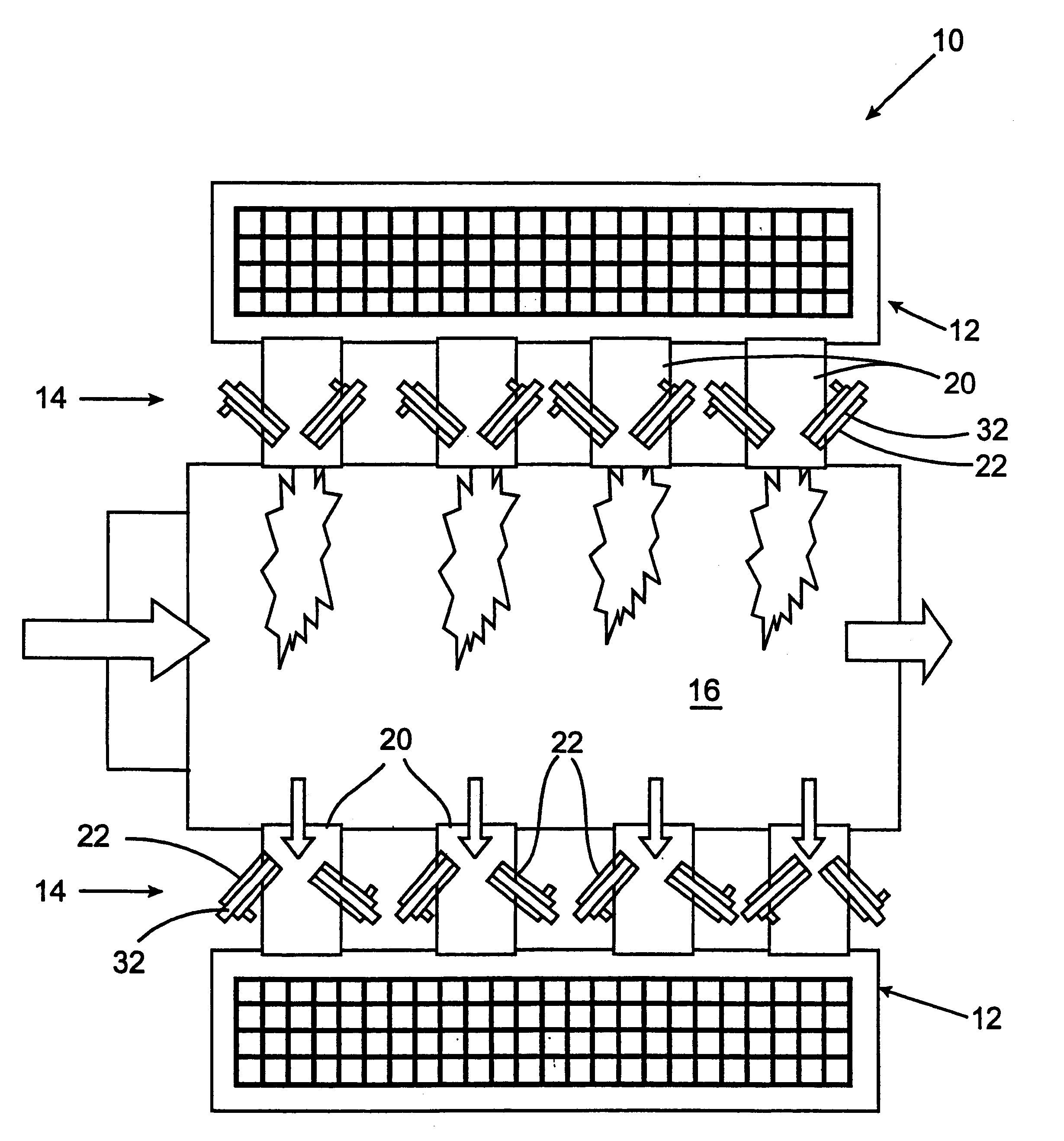
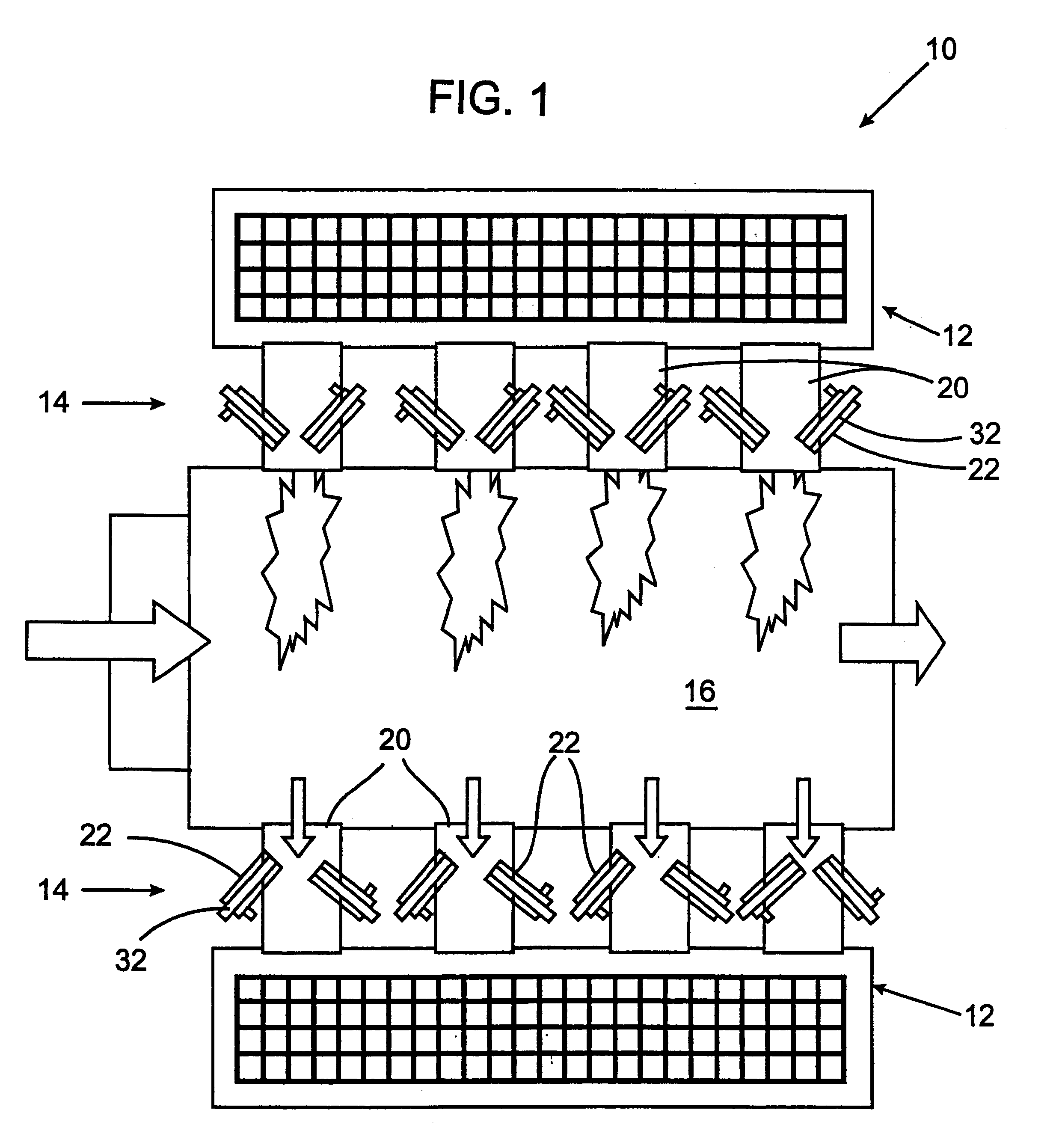
The combustion air passing around the burners 22 is often insufficient to provide the oxygen required for efficient combustion.

Method used


Image

  • Method of retrofitting a furnace to provide oxygen enrichment
  • Method of retrofitting a furnace to provide oxygen enrichment
  • Method of retrofitting a furnace to provide oxygen enrichment

Examples


Embodiment Construction

According to one example of an oxygen enrichment system according to the present invention, the oxygen concentration of combustion air is increased from about 20.9% to about 22.5%. With natural gas injected at 1000 Btu / cf through a 5 MMBtu / hr air-fuel-fired burner and combustion air delivered at the required stoichiometry through the combustion air port 20, this system will require about 900 scfh of oxygen delivered through the central oxygen lance. This amounts to about 7.8% oxygen for the overall stoichiometric combustion. The level of oxygen enrichment can be anywhere from about 3% to about 50% of the total oxygen requirement for the port. The oxygen pressure will be controlled to between about 1 and about 25 psig with gas velocities within the oxygen pipes maintained below about 100 ft / sec for safety reasons. The products of this incomplete oxy-fuel combustion (rich combustion) initiated with a natural gas jet core due to the injection of oxygen may contain an increased level of...


PUM

PropertyMeasurementUnit
temperatureaaaaaaaaaa
angleaaaaaaaaaa

Abstract

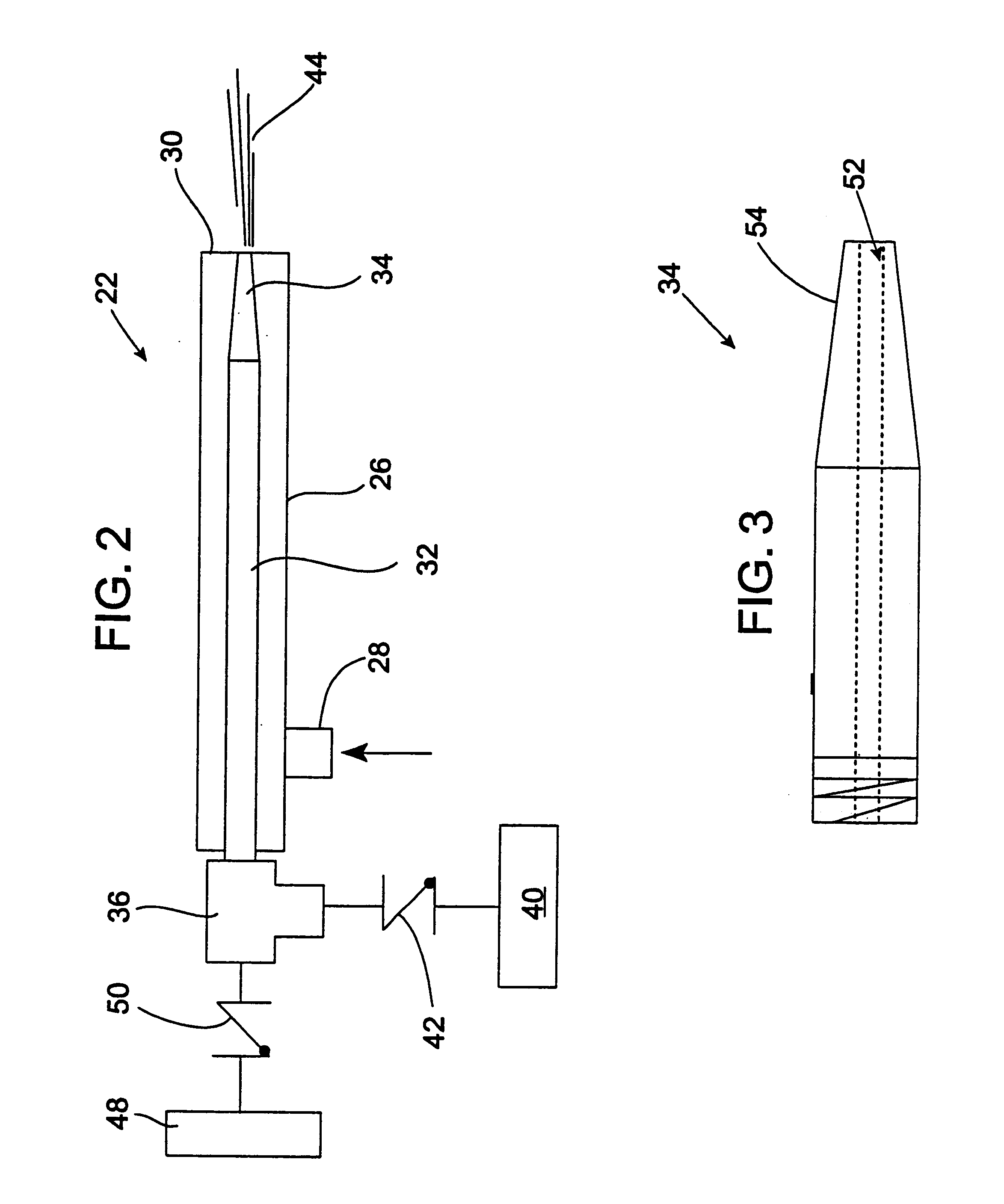
An oxygen enrichment system is provided which uses the existing air / fuel burners of a regenerative furnace to distribute additional oxygen to the burners for increased efficiency, and reduced nitrous oxide emissions. The centrally positioned cooling air lances in the burners of a regenerative furnace are modified to deliver oxygen when the burners are firing for oxygen enrichment. During the burmer firing cycle, oxygen is delivered from an oxygen supply through the oxygen lance to provide a central oxygen jet. The fuel is delivered concentrically around the oxygen jet. During the non-firing cycle of the burner, cooling air or other cooling fluid is delivered from the cooling air supply through the oxygen jet for cooling the offside of the furnace.

Description

1. Field of the InventionThe invention relates to a method and system for increasing the efficiency and productivity of a high temperature furnace, and more particularly, the invention relates to a device and method for operating air-fuel-fired burners in a furnace with oxygen enrichment for reducing Nitrous oxide emissions, increasing thermal efficiency, and improving productivity.2. Brief Description of the Related ArtIn known regenerative furnaces burner blocks having multiple firing ports are positioned on opposite sides or ends of the furnace combustion chamber. Each of the firing ports contains one or more burners for delivery of fuel into the combustion chamber. The firing ports also provide a combustion air supply around the burners. During furnace operation, the burners on opposite sides of the combustion chamber are operated alternately in a cyclic fashion. While the burners on one side of the combustion chamber are fired, cooling air is delivered to the opposite side of t...

Claims


Application Information

Patent Timeline
Patent Type & Authority Patents(United States)
IPC IPC(8): F23D14/78F23D14/00F23D14/22F23L15/00F23D14/32F23D14/72F23L15/02C21B9/10C21B9/14F23C99/00F23L7/00
CPCC03B5/2353F23D14/32F23D14/78F23L15/02F23D14/22C03B2211/30C03B2211/40C03B2211/60Y02E20/344Y02E20/34Y02P40/50Y02P40/57
Inventor JOSHI, MAHENDRA L.BORDERS, HARLEY A.CHARON, OLIVIER
Owner AIR LIQUIDE AMERICA INC
Learn More