Cyclone separator having a variable longitudinal profile

a cyclone separator and longitudinal profile technology, applied in the direction of filtration separation, separation process, vortex flow apparatus, etc., can solve the problem of additional material costs in producing each of the separators, current cyclones have a limitation that the geometry controls the particle removal efficiency, and current limitation in the design of cyclonic separators

Inactive Publication Date: 2001-08-21
OMACHRON INTPROP
View PDF99 Cites 92 Cited by
  • Summary
  • Abstract
  • Description
  • Claims
  • Application Information

AI Technical Summary

Benefits of technology

ofore been known. Accordingly, one advantage of the present invention is that a smaller number of cyclones may be employed in a particular application than have been used in the past. It will be appreciated by those skilled in the art that where, heretofore, two or more cyclones might have been required for a particular application, that only one cyclone may be required.

Problems solved by technology

Current cyclones have a limitation that the geometry controls the particle removal efficiency for a given particle diameter.
An example of the current limitation in cyclonic separator design is that which has been recently applied to vacuum cleaner designs.
Such an approach has two problems.
This requires additional space to house all of the separators and, secon

Method used


Image

  • Cyclone separator having a variable longitudinal profile
  • Cyclone separator having a variable longitudinal profile
  • Cyclone separator having a variable longitudinal profile

Examples


Embodiment Construction

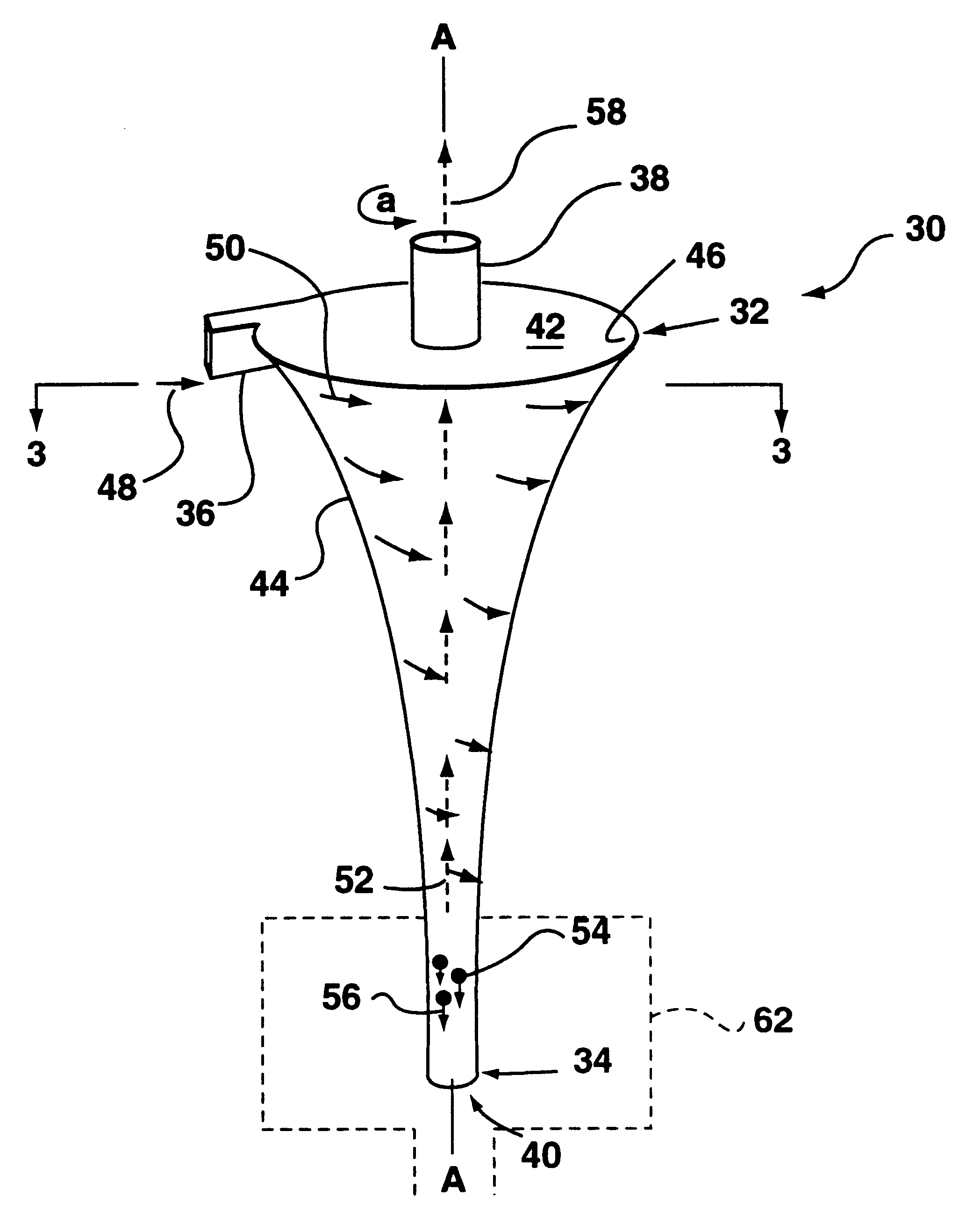
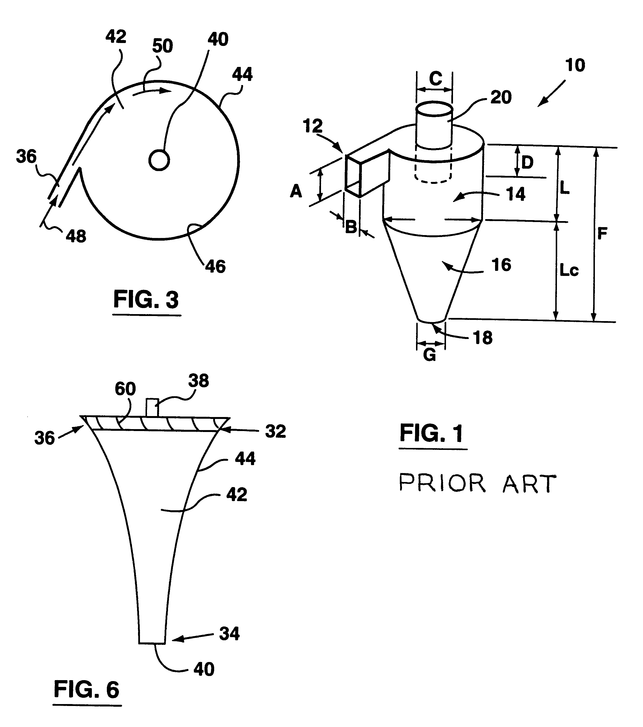
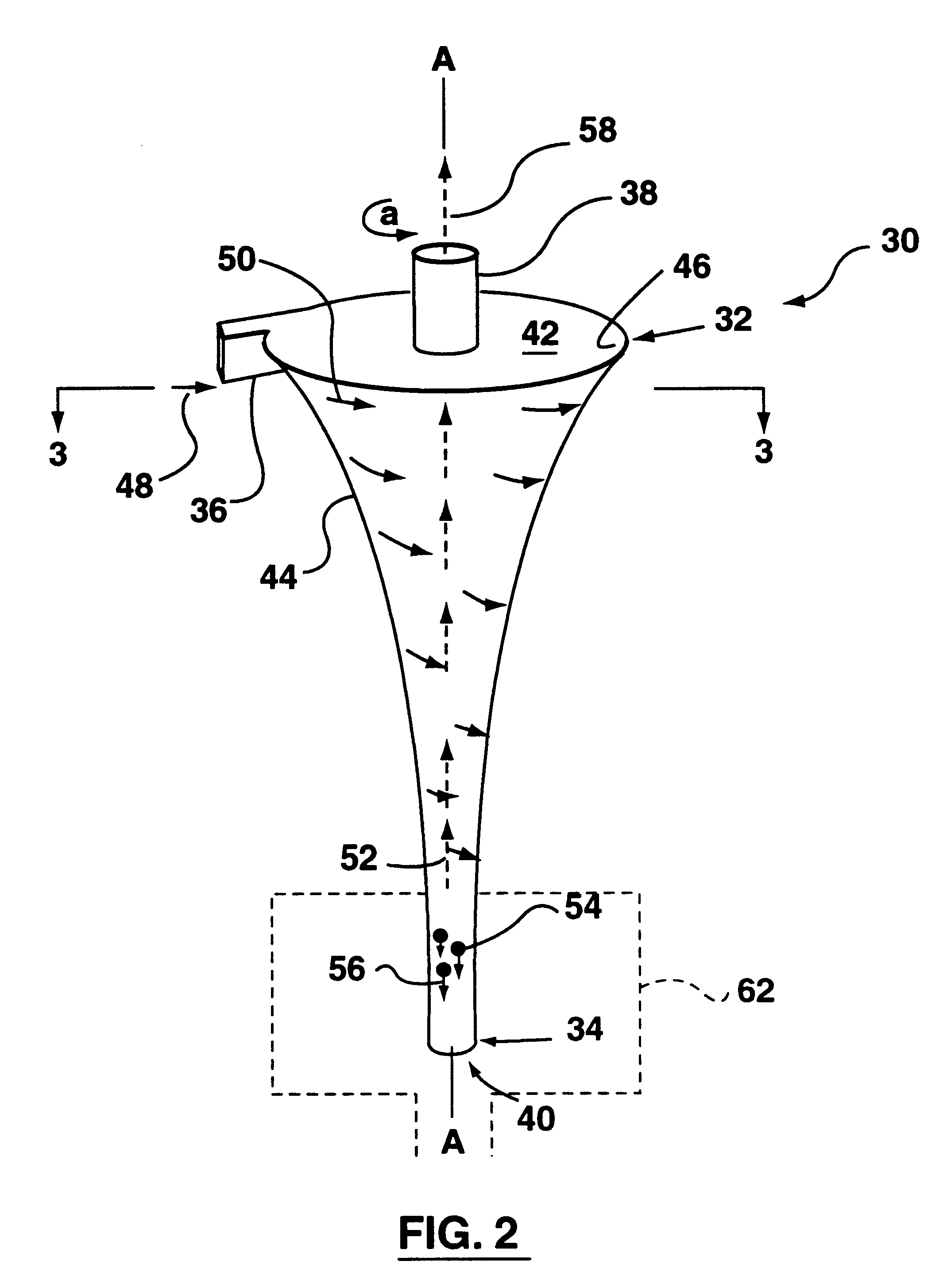
As shown in FIGS. 2, 5 and 7, cyclone separator 30 comprises a longitudinally extending body having a top end 32, a bottom end 34, fluid inlet port 36, a fluid outlet port 38 and a separated material outlet 40.

Cyclone separator 30 has a wall 44 having an inner surface 46 and defining a cavity 42 therein within which the fluid rotates.

Cyclone separator 30 has a longitudinally extending axis A--A which extends centrally through separator 30. Axis A--A may extend in a straight line as shown in FIG. 2 or it may be curved or serpentine as shown in FIG. 10.

As shown in FIGS. 2 and 5, cyclone separator 30 is vertically disposed with the fluid and material to be separated entering cyclone separator 30 at a position adjacent top end 32. As shown in FIG. 7, cyclone separator 30 is again vertically disposed but inverted compared to the position show in FIGS. 2 and 5. In this embodiment, fluid 48 enters cyclone separator 30 at a position adjacent bottom end 34 of the separator. It will be apprec...


PUM

PropertyMeasurementUnit
Angleaaaaaaaaaa
Densityaaaaaaaaaa
Accelerationaaaaaaaaaa

Abstract

A cyclone separator having an improved efficiency to remove a broader spectrum of contained particles is disclosed. The inner wall of the cyclone separator is configured to continuously impart changes in the acceleration of a fluid as it rotates within the cyclone cavity.

Description

This invention relates to an improved apparatus for separating a component from a fluid stream. In one embodiment, the fluid may be a gas having solid and / or liquid particles and / or a second gas suspended, mixed, or entrained therein and the separator is used to separate the particles and / or the second gas from the gas stream. In an alternate embodiment, the fluid may be a liquid which has solid particles, and / or a second liquid and / or a gas suspended, mixed, or entrained therein and the separator is used to remove the solid particles and / or the second liquid and / or the gas from the liquid stream. The improved separator may be used in various applications including vacuum cleaners, liquid / liquid separation, smoke stack scrubbers, pollution control devices, mist separators, an air inlet for a turbo machinery and as pre-treatment equipment in advance of a pump for a fluid (either a liquid, a gas or a mixture thereof) and other applications where it may be desirable to remove particula...

Claims


Application Information

Patent Timeline
IPC IPC(8): B04C3/00B04C5/081B04C5/00
CPCB04C3/00B04C5/081Y10S55/03B04C2003/003
Inventor CONRAD, WAYNE ERNESTCONRAD, HELMUT GERHARDSZYLOWIEC, TED
Owner OMACHRON INTPROP
Why Eureka
Try Eureka