Manipulation of acoustic waves using a functionally graded material and process for making the same

a functional graded material and acoustic wave technology, applied in the direction of sound producing devices, instruments, transmission, etc., can solve the problems of high capital investment and time-consuming, restricting choice, and reducing the ability to generate specific property gradients as a function of thickness

Inactive Publication Date: 2001-08-21
LIGHTPATH TECH INC
View PDF2 Cites 5 Cited by
  • Summary
  • Abstract
  • Description
  • Claims
  • Application Information

AI Technical Summary

Benefits of technology

In accordance with the present invention, a device for manipulation of acoustic waves is provided, comprising a functionally-graded material for interposing between a source of the acoustic waves and a target. The target may be an object upon which the acoustic waves are incident, such as a detector for measuring the intensity of the manipulated acoustic waves across the thickness, an imaging sensor, a specimen under non-destructive testing, or a recipient of focused acoustic energy, such as kidney or gall stones. The functionally-graded material has a gradient in one or both of the acoustic velocities (transverse or longitudinal) across the thickness. The gradient in acoustic velocities is achieved by creating a gradient in at least one of the following material properties: elastic modulus, Poisson's ratio, and density, that is perpendicular to a direction of propagation of the acoustic waves. The gradient is axial, as opposed to radial. Axial gradients having a parabolic or gaussian types of acoustic velocity gradients, such that the highest acoustic velocity is at the surfaces and the lowest acoustic velocity is in the center (positive), may be used for focusing. A negative axial gradient having a parabolic or guassian type acoustic velocity gradient, such that the lowest acoustic velocity is at the surfaces and the highest acoustic velocity is in the center, may be used for dispersing acoustic waves. These types of profiles can be fabricated by gluing or fusing two halves of a specific acoustic velocity profile at the high or low acoustic velocity faces, in subsequent text herein referred to as a biaxial. A continuously increasing, continuously decreasing, or any other special function of acoustic wave velocities may be used for wave steering.

Problems solved by technology

This places a restriction on the choice of chemicals that can be used in the fabrication of the final gradient profile, thereby reducing the ability to generate specific property gradients as a function of thickness.
Due to this fact, this technique is highly capital intensive and time-consuming.
The formation of the gel is restricted by the kinetics of the chemical reaction, which limits the available reactants for production of the gradient profile.
Furthermore, failure due to drying shrinkage places a limitation on the dimensions of the final product and is an inherent disadvantage to this technology.
Thus, obtaining large diffusion depths at a temperature below T.sub.g becomes difficult for reasonable amounts of time.
Surface modification of the material substrates using ion exchange or solid state diffusion imposes several limitations with regards to obtaining a particular property gradient.
The propagating wave would not see a large difference in acoustic velocity (transverse or longitudinal); therefore, there exists only a limited ability to manipulate the acoustic waves.
Secondly, this technique offers the ability to create a variety of functional distributions of a material property, but does not offer the flexibility to tailor a specific material property profile.
Thirdly, the total distance across which the material property gradient exists is limited due to the nature of ion exchange phenomena and solid state diffusion.
This does not allow for the fabrication of material property gradients across a large thickness.

Method used


Image

  • Manipulation of acoustic waves using a functionally graded material and process for making the same
  • Manipulation of acoustic waves using a functionally graded material and process for making the same
  • Manipulation of acoustic waves using a functionally graded material and process for making the same

Examples


example

A piece of homogeneous glass (12.times.12.times.60 mm), a cemented biaxial (12.times.12.times.60 mm), and a fused biaxial (12.times.12.times.20 mm) were tested for the ultrasonic wave (USW) intensity across the thickness (essentially the focusing behavior). The acoustic velocity gradients were obtained by fusion / diffusion of base glasses with the material properties listed in the Table below. The homogeneous glass is glass B in the Table, while the cemented and fused biaxials each comprise two monoaxial slabs of glass of three layers each, fused and diffused (glasses A, B, and C). Glasses A, B, and C are each commercially-available lead silicates.

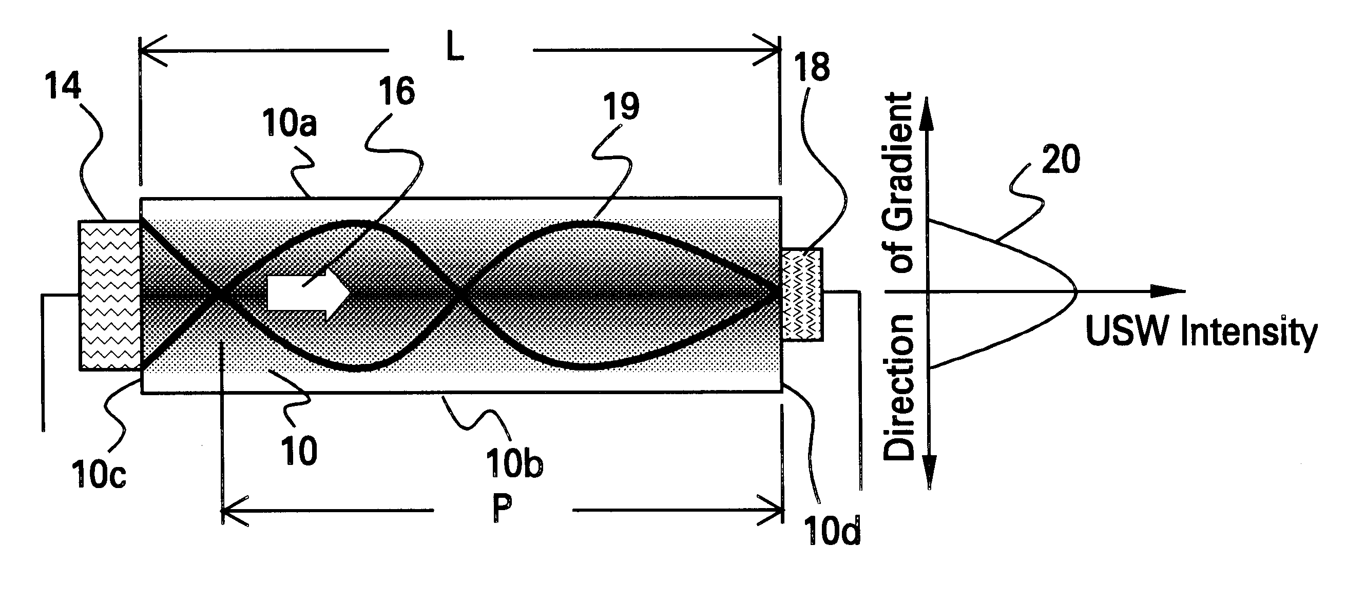
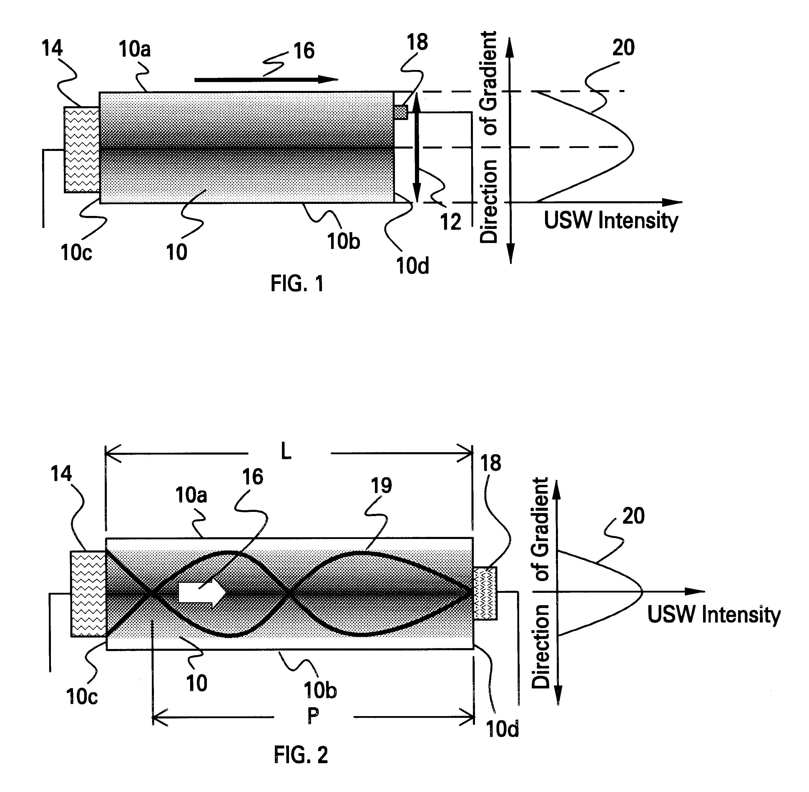
The two axial gradient pieces were joined along their low acoustic velocity faces, providing a high-low-high slab for focusing USW. A 14 MHz transducer 14 was used for sending the USW into the material. The detector 18 for sensing the USW intensity was moved along the gradient direction 12.

The samples were prepared as follows: For making an...

second embodiment

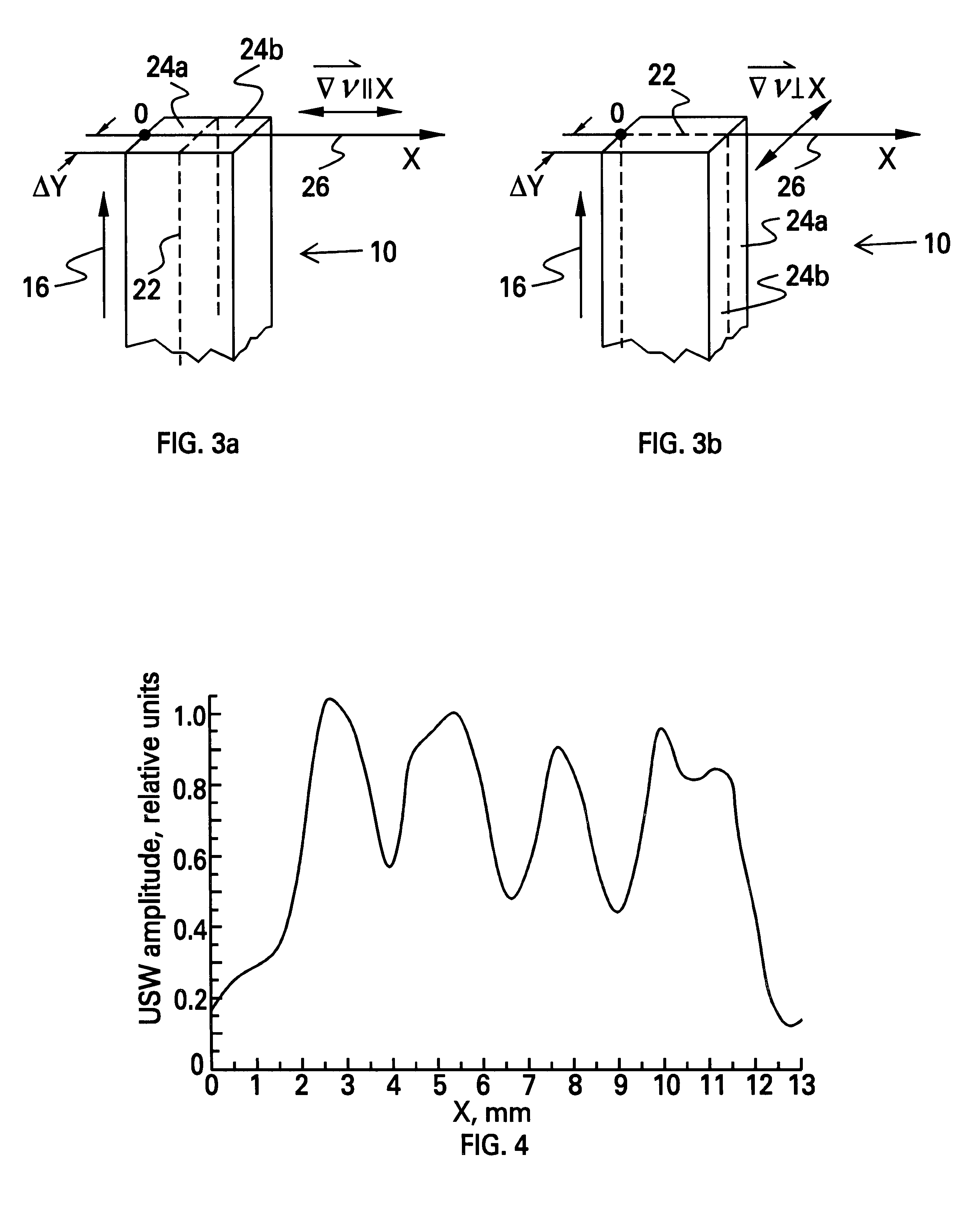
FIGS. 3a and 3b schematically illustrate the scanning of the sample butt-end by the USW detector 18 in two directions for the biaxial gradient slabs 10. In one embodiment, cement layer 22 was used to join two separate glass pieces 24a, 24b to form the slab 10. In a second embodiment, the two separate glass pieces 24a, 24b were joined along the interface 22 by fusing them together. The detector 18 moved in the direction denoted 26. In FIG. 3a, the detector 18 was moved such that the gradient direction of the acoustic velocity, .gradient..sub..nu. +L , was parallel to the X-direction. In FIG. 3b, the detector 18 was moved such that .gradient..sub..nu. +L was perpendicular to the X-direction. .DELTA.Y is the shift of the detector 18 from the sample butt-end edge.

FIG. 4 depicts the USW amplitude measured along the X-direction for the homogeneous glass B. .DELTA.Y was 6 mm. In this case, there was considerable symmetry in the USW intensity about the central plane, as seen in Curve 28. Th...


PUM


Abstract

A device for manipulation of acoustic waves is provided, comprising a functionally-graded material for interposing between a source of the acoustic waves and a target, which may be a detector of manipulated acoustic waves. The functionally-graded material has a gradient in acoustic wave velocity which is obtained by the generation of a gradient in at least one of the following properties: elastic modulus, Poisson's ratio, and density, that is perpendicular to a direction of propagation of the acoustic waves. The gradient is axial. Biaxial acoustic velocity gradients may be used for focusing/waveguiding (high-low-high) or dispersing (low-high-low), while monoaxial acoustic velocity gradients may be used for wave steering. Also in accordance with the present invention, a method of making the device is provided, comprising: (a) providing the source of acoustic waves; (b) providing the target for acoustic waves, e.g., detector of manipulated acoustic waves; (c) providing the functionally-graded material having a gradient in at least one material property; and (d) interposing the functionally-graded material between the source of acoustic waves and the target for acoustic waves such that the gradient is perpendicular to a direction of propagation of the acoustic waves. The functionally-graded material so provided can be used to manipulate, i.e., focus, disperse, steer, waveguide acoustic waves for applications such as, acoustoelectronics, acoustooptics, SONAR, ultrasonic imaging, non-destructive testing (NDT), etc.

Description

The present invention is generally directed to the manipulation (e.g., focusing, dispersing, steering, waveguiding, etc.) of acoustic (sound) waves, and, more particularly to the use of materials having a gradient in acoustic velocities (transverse and longitudinal). These velocity gradients are obtained by generating a gradient in one or more of the following properties: elastic modulus, Poisson's ratio, and density.Acoustic waves, e.g., ultrasonic waves, find use in a variety of applications. In many such applications, it is desired to manipulate the acoustic waves in order to focus, disperse, steer, waveguide, or otherwise alter them. There are several different techniques used to fabricate materials with gradients in material properties, such as ion exchange, chemical vapor deposition (CVD), sol-gel, etc.Chemical vapor deposition techniques can be used to fabricate a gradient in material properties. CVD requires that the reactants be present in the gaseous phase and that the rea...

Claims


Application Information

Patent Timeline
Patent Type & Authority Patents(United States)
IPC IPC(8): G10K11/30G10K11/00
CPCG10K11/30
Inventor TYAGI, VINEETTINCH, DAVID A.
Owner LIGHTPATH TECH INC
Why Eureka
Try Eureka