Barrel-polishing apparatus

a technology of barrel-polishing and axial portion, which is applied in the direction of chemistry apparatus and processes, manufacturing tools, edge grinding machines, etc., can solve the problems of reducing the surface pressure of the polishing medium applicable to the workpiece, preventing the enhancement of the polishing efficiency, and leaving the axial portion of the workpiece unpolished, etc., to achieve the effect of enhancing the polishing efficiency of the barrel-polishing operation

Inactive Publication Date: 2001-08-28
KAWASAKI SHUJI
View PDF8 Cites 16 Cited by
  • Summary
  • Abstract
  • Description
  • Claims
  • Application Information

AI Technical Summary

Benefits of technology

It is the first object of the present invention to provide, in order to obviate the shortcomings inherent in the first prior art, a barrel-polishing apparatus having flowing polishing mediums, wherein a pressure level of polishing mediums applicable to a workpiece is maintained to a predetermined value or larger by preventing the polishing mediums from bulging, thereby enhancing the polishing efficiency of the barrel-polishing operation (hereinafter referred to the "first and second inventions").
Also, if the base is slanted downwardly towards the polishing medium bath, the workpiece can easily be moved reciprocally with respect to the polishing medium bath.

Problems solved by technology

However, because of the reasons that the polishing mediums tend to bulge over the workpiece due to flow of the polishing mediums in the former polishing apparatus and due to flow of the polishing mediums caused by vibrations of the workpiece in the latter polishing apparatus, a surface pressure of the polishing mediums applicable to the workpiece is readily reduced to discourage the enhancement of the polishing efficiency.
However this conventional barrel-polishing method has such shortcomings that in case the workpiece has a hole around its axis, the polishing mediums readily pass through the hole when they flow along the workpiece and therefore, they hardly stay at the axial portion of the workpiece, with the result that the axial portion of the workpiece is left unpolished.
However, this conventional barrel-polishing apparatus has such shortcomings that since the entire polishing mediums must be flowed in order to flow the polishing mediums, the apparatus itself inevitably becomes large scale.
However, in such a conventional polishing apparatus, since the partial wear of the aggregate of polishing mediums is determined based on the perception or experience of the operator, much labor is required.
In addition, since the result of determination is different depending on each operator, a constant polishing effect is difficult to obtain in an efficient manner.

Method used


Image

  • Barrel-polishing apparatus
  • Barrel-polishing apparatus
  • Barrel-polishing apparatus

Examples


eighth embodiment

(Eighth Embodiment)

Description of those portions in common with the embodiments of the sixth and seventh inventions is omitted.

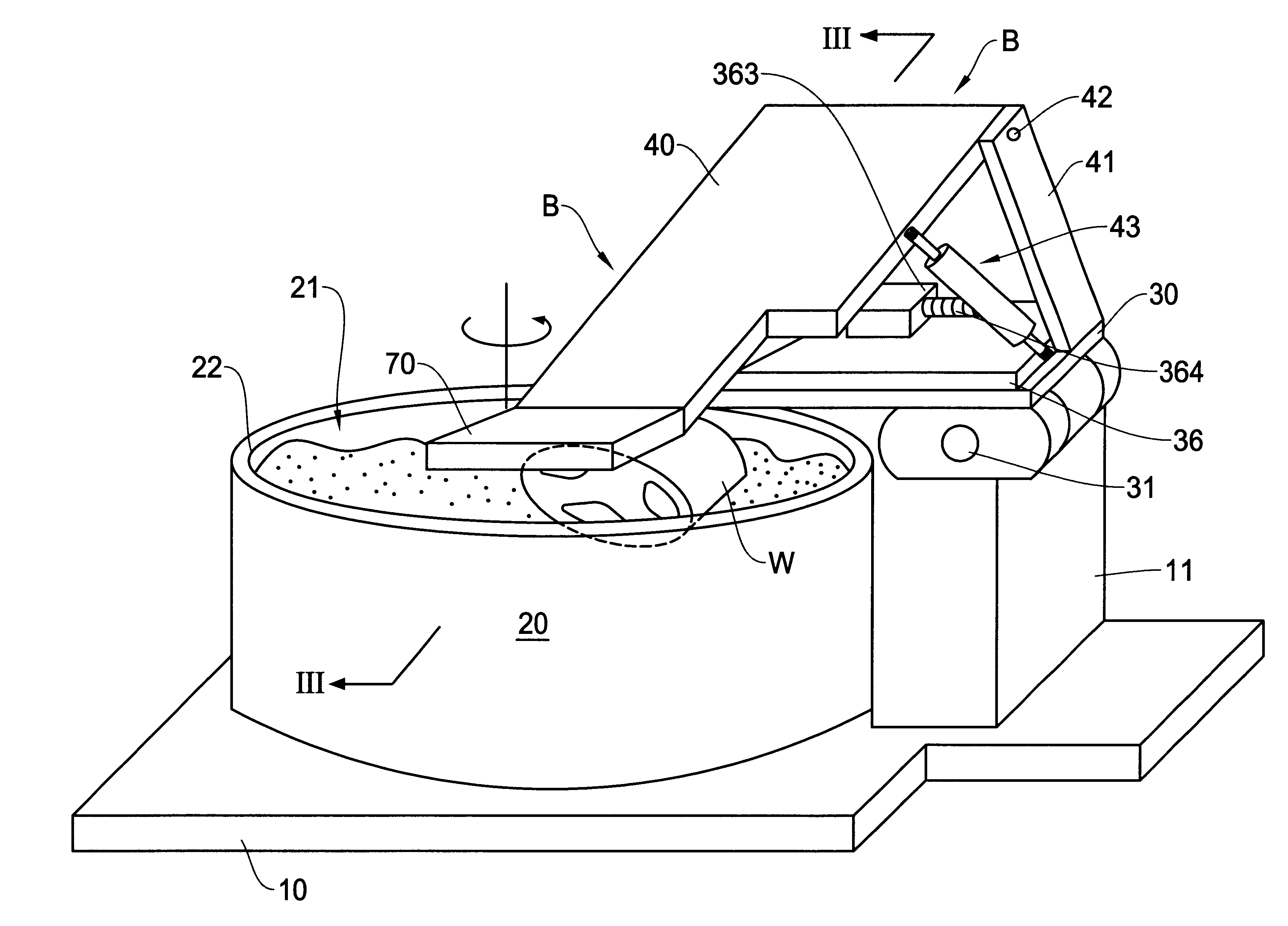
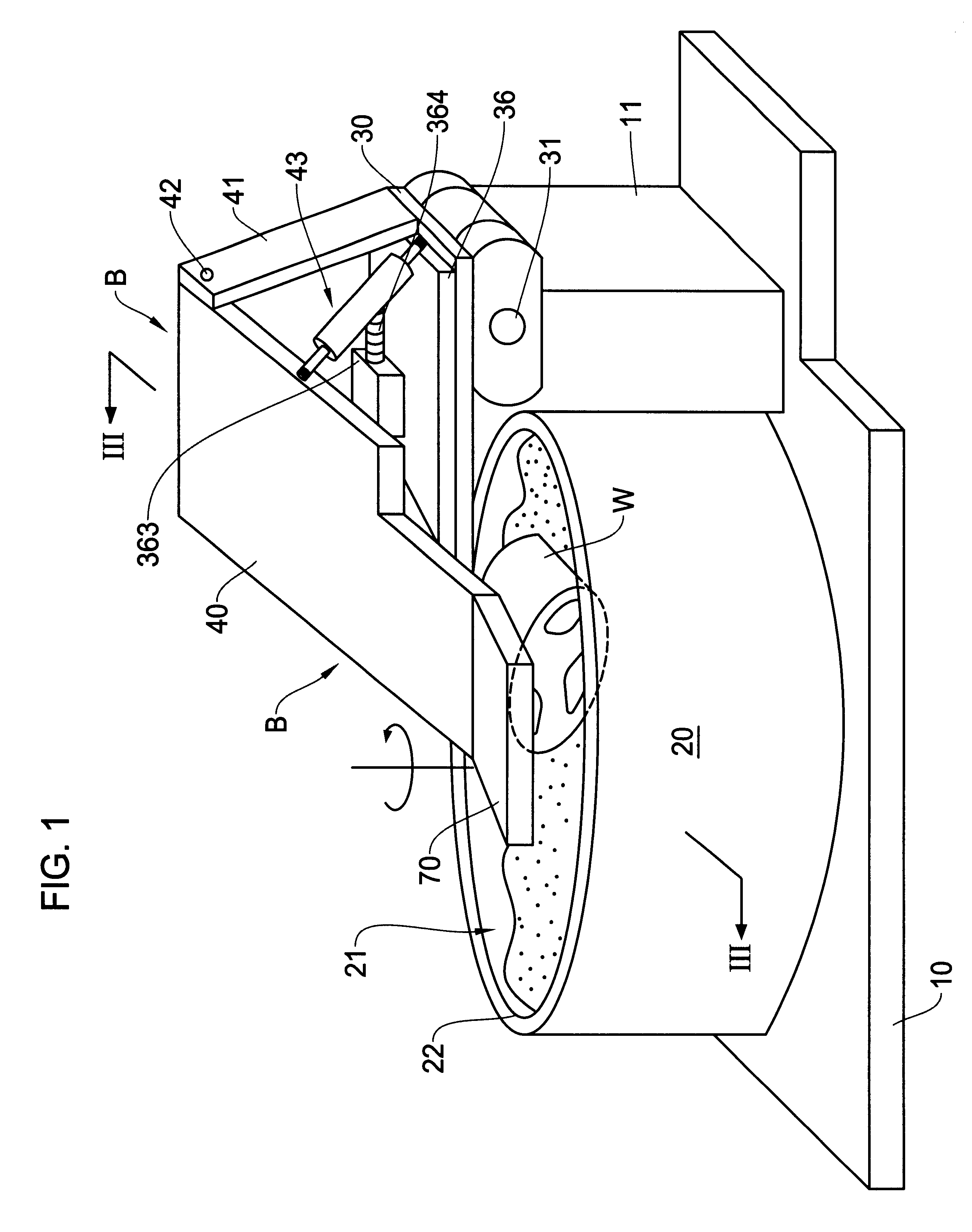
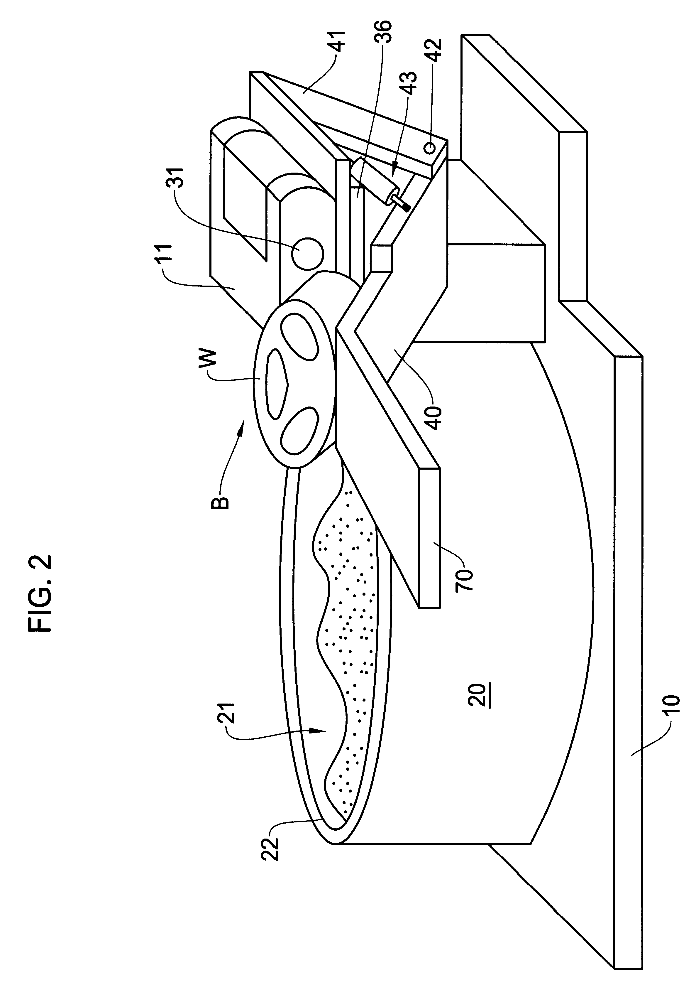
Reference numeral 61 denotes a rotational drive portion (this rotational drive portion corresponds to the "electrically-operated rotary means" of the eighth invention). The rotational drive portion 61 is mounted on the slide plate 50. The rotational drive portion 61 comprises an engine (AC or DC engine) and a reduction gear unit. The rotational drive portion 61 can provide a circular motion through the rotary shaft 60. The rotary shaft 60 extends along the axis of the bolt member 511, i.e., in the slanting direction of the base 40.

The engine (AC or DC) of the rotational drive portion 61 is driven by a power source 92. At that time, the electric current supplied to the engine is measured by a current detector means 93. The result of measurement thus obtained is sent to a control unit 94 where the result of measurement is compared with a preset value (this pre...


PUM


Abstract

There is disclosed a barrel-polishing apparatus comprising a polishing medium bath with polishing mediums received therein, a base, an arm mounted on the base, and a workpiece attachment device mounted on a distal end portion of the arm and adapted to attach a workpiece to the arm, wherein the polishing mediums are caused to flow within the polishing medium bath by an appropriate device and a pressing plate for pressing the polishing mediums is mounted on the polishing medium bath. A barrel-polishing method is also disclosed.

Description

This invention relates to a barrel-polishing apparatus and a barrel-polishing method.PRIOR ART(First Prior Art and Shortcomings Thereof)In conventional barrel-polishing apparatuses, it is a usual practice that a workpiece is polished while flowing polishing mediums or while vibrating a workpiece in stationary polishing mediums.However, because of the reasons that the polishing mediums tend to bulge over the workpiece due to flow of the polishing mediums in the former polishing apparatus and due to flow of the polishing mediums caused by vibrations of the workpiece in the latter polishing apparatus, a surface pressure of the polishing mediums applicable to the workpiece is readily reduced to discourage the enhancement of the polishing efficiency.(Second Prior Art and Shortcomings Thereof)Conventionally, there is known a typical method for polishing a workpiece. In this method, a workpiece is placed in polishing mediums such that an upper end side of a surface-to-be-polished of the wo...

Claims


Application Information

Patent Timeline
Patent Type & Authority Patents(United States)
IPC IPC(8): B24B31/00B24B31/12
CPCB24B31/003B24B31/12Y10S451/91
Inventor KAWASAKI, SHUJI
Owner KAWASAKI SHUJI
Why Eureka
Try Eureka