Radial blower, particularly for heating and air conditioning systems in automobiles

a technology of radiator blower and air conditioner, which is applied in the direction of positive displacement liquid engine, piston pump, liquid fuel engine, etc., can solve the problems of affecting the service life of the blower motor, difficult to adequately cool the blower motor itself, and generally limited space available in the automobile for installing a heating, venting and air cooling system, so as to reduce the temperature of the motor components and reduce the service life of the drive motor and thus of the system. , the effect of increasing the servi

Inactive Publication Date: 2001-09-04
BROSE FAHRZEUGTEILE GMBH & CO KG HALLSTADT (DE)
View PDF7 Cites 51 Cited by
  • Summary
  • Abstract
  • Description
  • Claims
  • Application Information

AI Technical Summary

Benefits of technology

to avoid or overcome the disadvantages of the prior art, particularly to increase the operational life of vehicle heating and cooling systems, especially of the motor of such system;
to improve the cooling air flow through the blower motor generally at all blower motor r.p.m.s, and particularly in a normal r.p.m. range where the fan does not run at high speed, to keep particularly the motor at a non-critical temperature range.
Preferably, the fan disk according to the invention has a plurality of partially-hooded openings which are so constructed that a forward or leading end of an opening relative to the direction of rotation of the fan wheel, is partly covered by the respective raised hood that is open at a trailing or rear end facing opposite to the direction of rotation of the fan wheel. As the fan wheel rotates, a negative pressure is generated by the plurality of hoods each covering at least partly a respective opening. The negative pressure occurs just behind the hood above the opening on the side of the fan disk facing away from the drive motor. This negative pressure or suction increases the airflow through the blower drive motor, thereby providing effective cooling of the motor and its components. The cooling air passing through the blower drive motor is pulled through the partially-hooded openings in the fan disk into the intake or suction chamber in the spiral housing of the blower wheel, mixed with the main airflow volume, and transported to the blower air discharge opening or openings. Increasing airflow through the motor reduces the temperature of the motor components to an uncritical temperature range whereby the service life of the drive motor and thus of the system is increased. The shape of the hoods also contributes to a quieter blower operation. Furthermore, because of its compact construction, the radial blower can be used advantageously in automobiles that have very little available space.
It is advantageous to construct the fan wheel or impeller with its hub, its fan ring with the fan blades, and the fan disk with its openings and hoods as a single component, preferably as an injection-molded part, preferably made of a plastic material.

Problems solved by technology

The space available in an automobile for installing a heating, venting and air cooling system is generally rather limited.
However, in such a construction it is difficult to adequately cool the blower motor itself.
However, especially during extended operation, the components become too hot, which has a negative effect on the service life of the blower motor.
This fan wheel, however, is less suitable for applications that require quiet operation because the openings in the fan disk allow "short-circuit" flow between the pressure side and the suction side and, thus, the blower tends to be noisy.

Method used


Image

  • Radial blower, particularly for heating and air conditioning systems in automobiles
  • Radial blower, particularly for heating and air conditioning systems in automobiles
  • Radial blower, particularly for heating and air conditioning systems in automobiles

Examples


Embodiment Construction

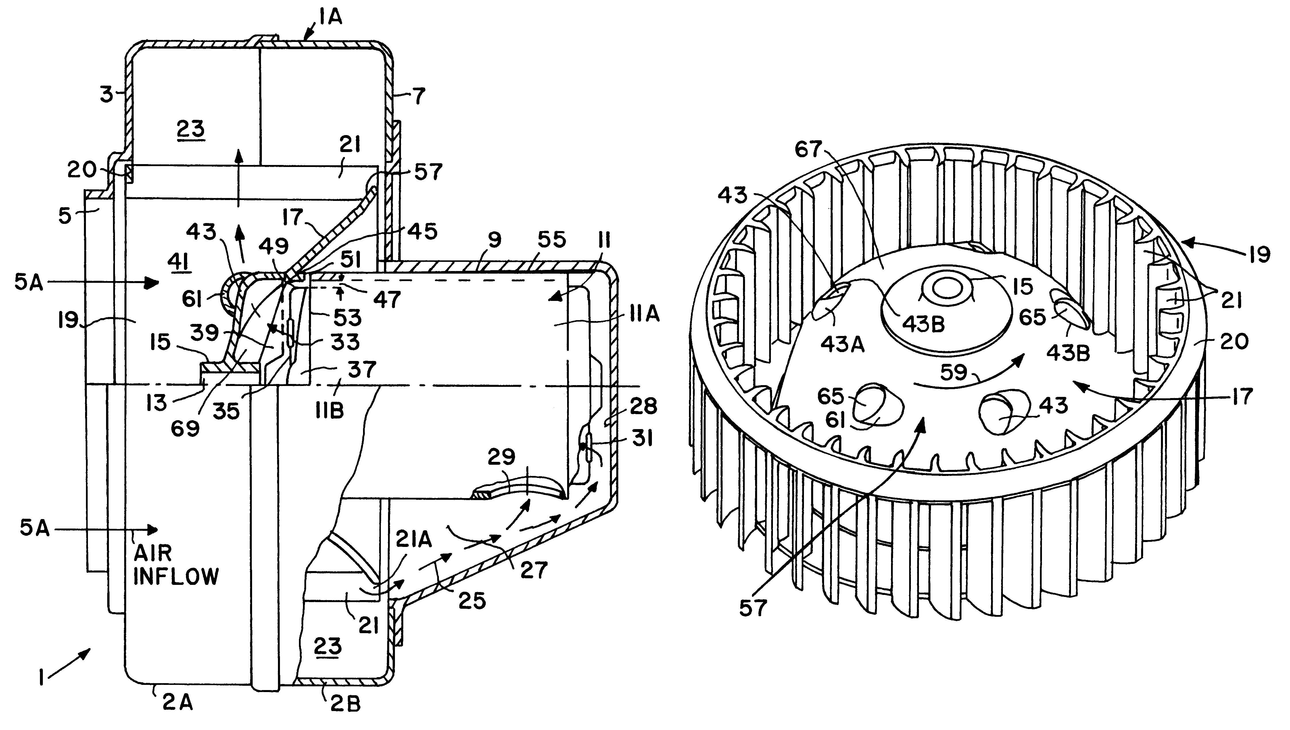
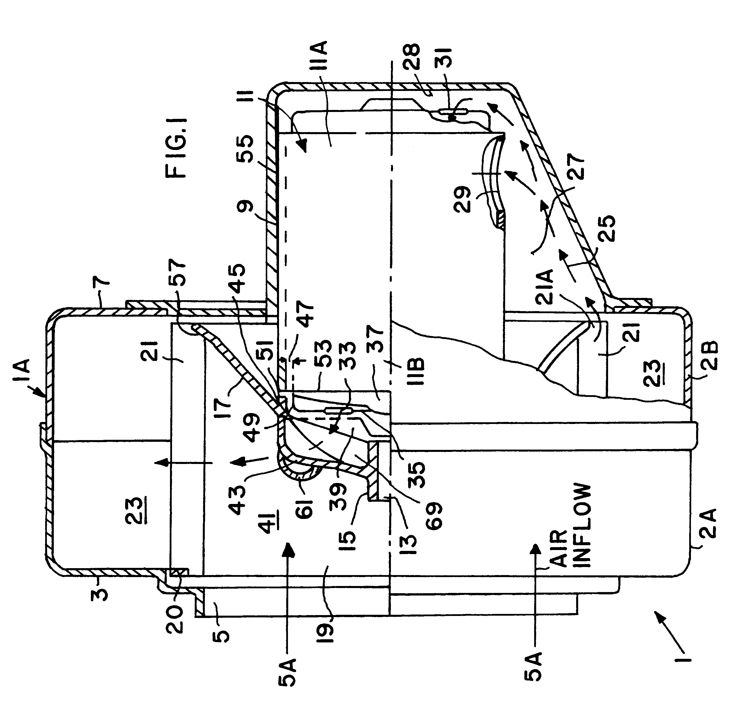
FIG. 1 shows a first embodiment of a radial blower 1, particularly for heating and air-conditioning systems in automobiles. The blower 1 has a spiral blower housing 1A which is preferably divided into two separable shell sections 2A and 2B for easy access. A front wall 3 of the blower housing shell section 2A has an air intake opening 5. Arrows 5A show the air inflow. A housing rear wall 7 has attached thereto a closed housing extension 9. A blower drive motor 11 is mounted in the blower housing so that a rear portion 11A of the blower drive motor 11 is enclosed in the extension 9. The drive motor 11 is for example an electric motor, but could be any other motor such as a hydraulic motor. For purposes of noise insulation, the drive motor 11 or rather its housing 55 is surrounded on all sides by an air gap except where the motor housing 55 is secured to the blower housing extension 9, for example by lands not shown.

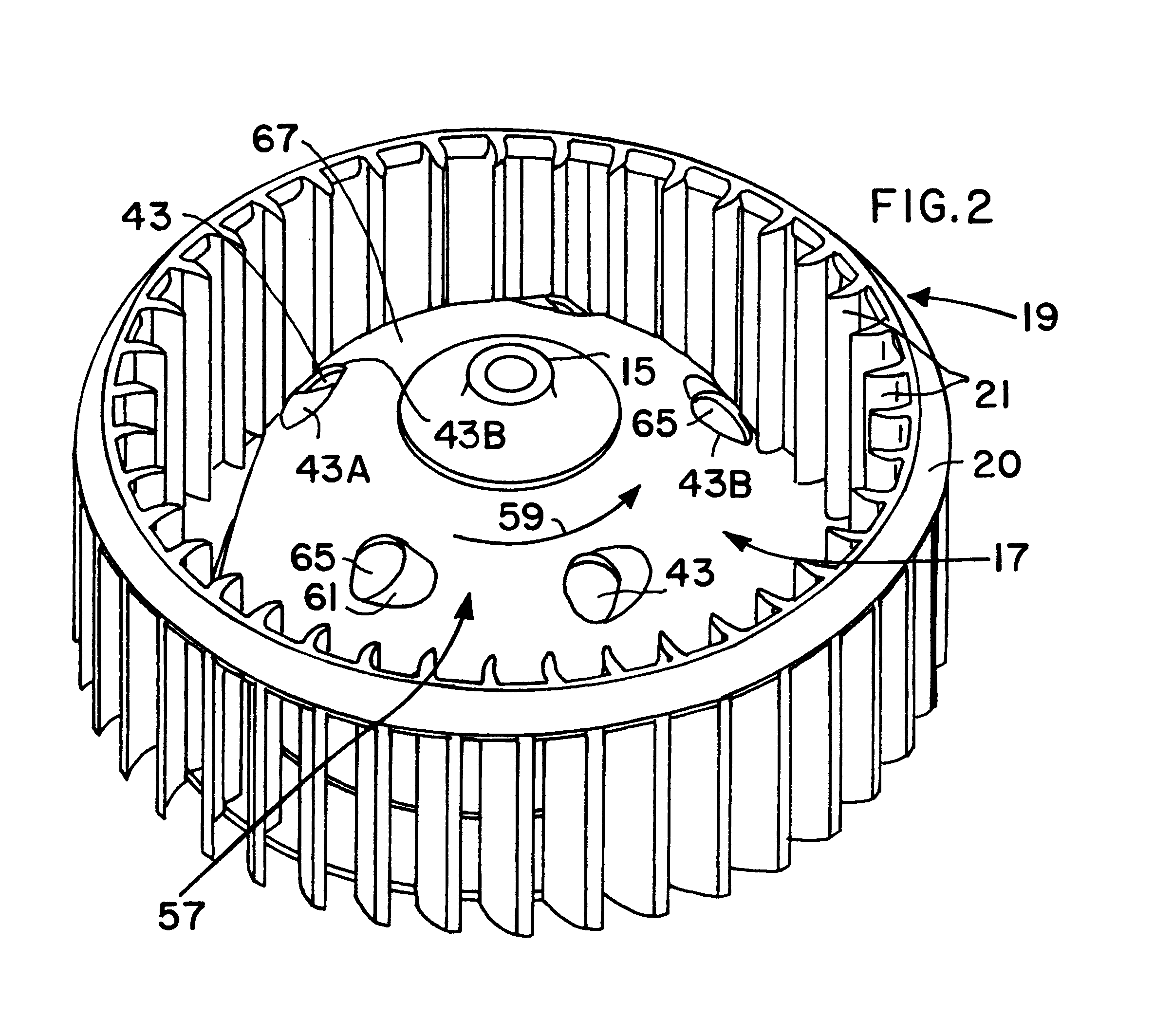
A fan wheel 19 having a vaulted or dished fan disk 17 is fastened by ...


PUM


Abstract

A radial blower, particularly for heating and air-conditioning systems for automobiles, has a spiral blower housing that is provided with an air intake (5) in a housing lateral wall and with an air outlet out of the spiral housing. A blower drive motor for a fan wheel is mounted to the housing with the fan wheel positioned in the spiral housing to face the air intake (5). The fan wheel has a fan ring with fan blades and a hub. The fan ring and the hub are connected to each other by a shell shaped vaulted or dished fan disk, which at least partly surrounds the drive motor. Fan disk openings (43) permit at least a portion of cooling air flowing through the drive motor to be discharged through the disk openings (43) into a blower air discharge chamber (23) in the spiral housing. The openings in the fan disk are formed to generate a negative pressure at these openings on a fan disk surface facing away from the drive motor whereby airflow through the motor is increased because the negative pressure draws more cooling air through the motor. The suction is further increased by streamlined hoods (61) covering part of the fan disk openings on the disk surface facing away from the motor. The increased airflow through the drive motor increases the service life of the blower and of the motor.

Description

The invention relates to a radial blower, particularly for heating and air-conditioning systems in automobiles. Such blowers have a spirally shaped blower housing with air inlets in one housing sidewall and a blower motor mounted to the blower housing, so that a fan wheel driven by the motor faces the air inlets.BACKGROUND INFORMATIONThe space available in an automobile for installing a heating, venting and air cooling system is generally rather limited. Often, a centrifugal blower is used for circulating air, particularly to achieve a desired quiet operation. A space-saving construction of such a blower is achieved if the air is drawn directly into the blower at an intake positioned in a blower housing wall opposite the wall to or on which an electric blower motor is mounted. However, in such a construction it is difficult to adequately cool the blower motor itself.German Patent Publication DE 195 47 674 A1 discloses a radial blower, particularly for heating and air-conditioning sy...

Claims


Application Information

Patent Timeline
Patent Type & Authority Patents(United States)
IPC IPC(8): F04D25/08F04D25/02F04D29/28
CPCF04D29/283F04D25/082F04D29/5806
Inventor FACKELMANN, WALTERHILLRICHS, HEINRICH
Owner BROSE FAHRZEUGTEILE GMBH & CO KG HALLSTADT (DE)
Why Eureka
Try Eureka