Polarization control optical space switch

a technology of optical space switch and polarization control, applied in the field of optical space switch, can solve problems such as crosstalk from path to path, differences in transmission loss,

Inactive Publication Date: 2001-09-04
FUJITSU LTD
View PDF19 Cites 18 Cited by
  • Summary
  • Abstract
  • Description
  • Claims
  • Application Information

AI Technical Summary

Problems solved by technology

The prior art polarization control optical space switch has the further problem that the number of switch elements for light to pass through varies depending on the path to be set, resulting in differences in the transmission loss and crosstalk from path to path.

Method used


Image

  • Polarization control optical space switch
  • Polarization control optical space switch
  • Polarization control optical space switch

Examples


embodiment 1

[Embodiment 1]

(Hardware configuration of the polarization control optical switch)

FIG. 3 shows the hardware configuration of a polarization control optical switch according to Embodiment 1.

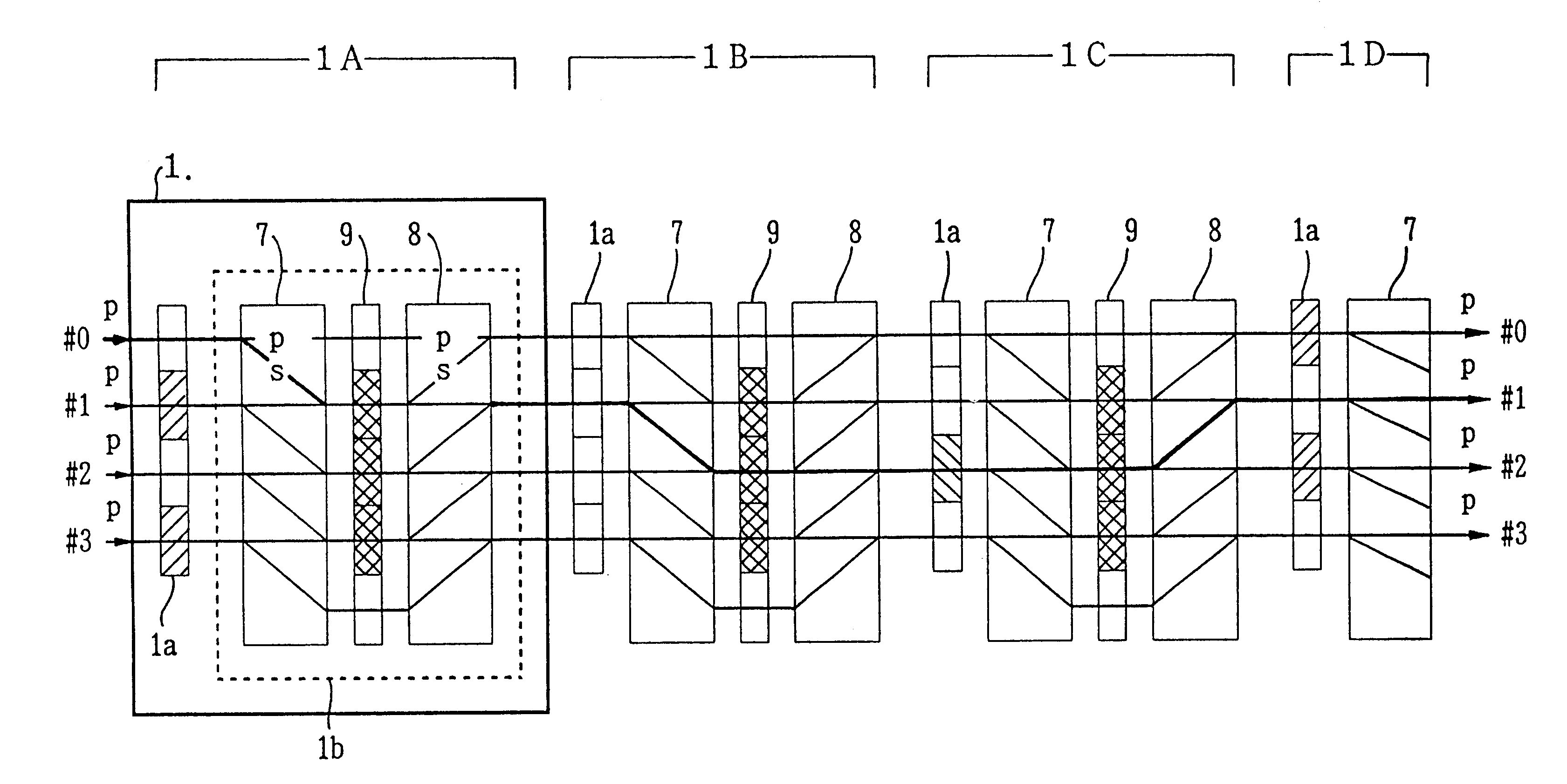
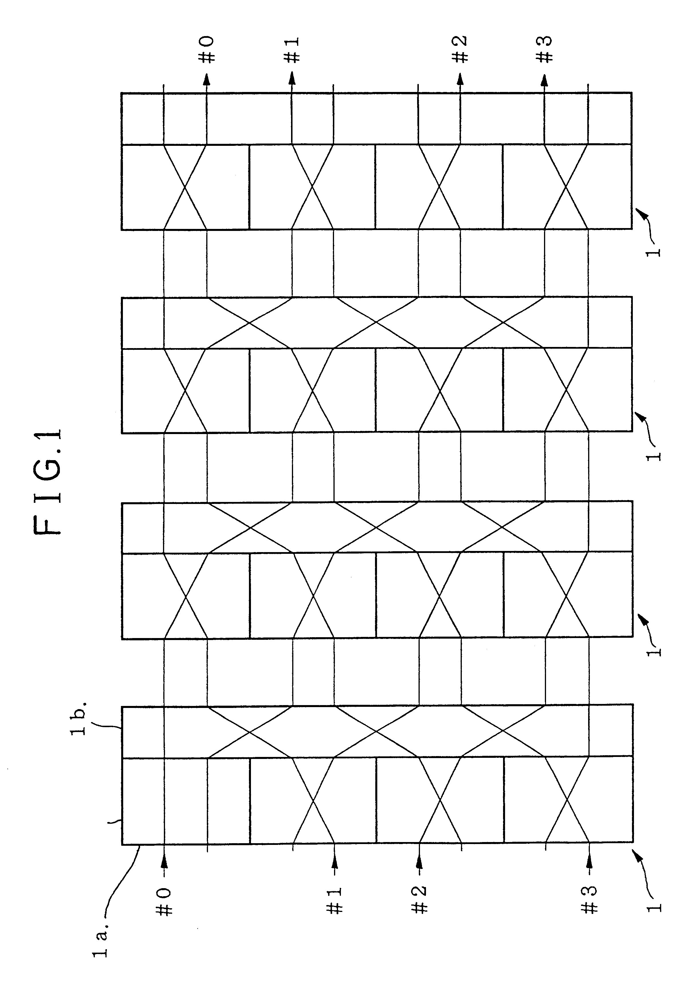
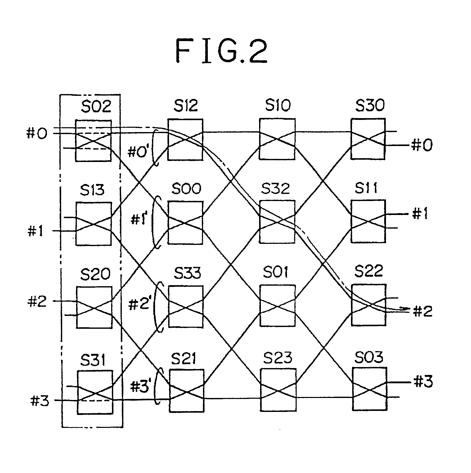
The polarization control optical switch 1 shown in FIG. 3 is a hardware implementation of m switch elements arranged in each column in an m (rows).times.m (columns) matrix in the functional configuration shown in FIG. 2.

The polarization control optical switch 1 comprises a light path routing element 1b and a polarization controller 1a placed on the input side of the light path routing element 1b.

The polarization controller 1a performs two functions: one is to transmit incident light information without change in its polarizing direction; and the other is to rotate its polarizing direction through 90.degree. for output. Switching between these two functions is accomplished by the presence or absence of voltage application. For example, the polarization controller 1a may be so configured that when no...

embodiment 2

[Embodiment 2]

(Hardware configuration of the polarization control optical switch)

FIG. 7 shows the configuration of a polarization control optical switch 1 according to Embodiment 2.

The polarization control optical switch 1 has eight input light paths and eight output light paths.

The light path routing element 1b of this polarization control optical switch 1 comprises: a polarization splitter 20 which transmits p-polarized light and reflects s-polarized light; a reflected-side .lambda. / 4 wavelength plate 30 placed on the output side of light information reflected by the polarization splitter 20; a reflected-side reflection block 50 placed on the output side of the reflected-side .lambda. / 4 wavelength plate 30; a transmitted-side .lambda. / 4 wavelength plate 40 placed on the output side of light information transmitted by the polarization splitter 20; and a transmitted-side reflection block 60 placed on the output side of the transmitted-side .lambda. / 4 wavelength plate 40.

The polariza...

embodiment 3

[Embodiment 3]

(Hardware configuration of the polarization control optical switch)

FIG. 8 shows the hardware configuration of a polarization control optical switch according to Embodiment 3.

This polarization control optical switch has four inputs and four outputs.

As in Embodiment 1, the polarization control optical switch 1 comprises a polarization controller 1a and a light path routing element 1b.

The polarization controller 1a works to rotate, or not rotate, the polarizing direction of incident light through 90.degree., depending on the presence or absence of voltage application. More specifically, the polarization controller 1a consists of polarization control elements, PLC0-PLC3, the number of which is equal to the number of input light paths. Each of the polarization control elements, PLC0-PLC3, works to rotate, or not rotate, the polarizing direction of incident light information through 90.degree., depending on the presence or absence of voltage application.

For example, in the c...


PUM

PropertyMeasurementUnit
angleaaaaaaaaaa
reflecting angleaaaaaaaaaa
incident angleaaaaaaaaaa

Abstract

The present invention,is directed to an optical space switch accommodating a plurality of input light paths and output light paths. The optical space switch comprises a plurality of polarization control optical switches, each consisting essentially of: polarization control means having elements, one for each input light path, for rotating through 90° the polarizing direction of light information incident from each input light path or otherwise retaining the polarizing direction thereof for output; and a light path routing element for routing the light path for the light information output from the polarization control means in accordance with the polarizing direction of the light information. These polarization control optical switches are arranged in a matrix pattern or coupled in cascade to implement a polarization control optical space switch.

Description

(1) Field of the InventionThe present invention relates to an optical space switch that is used to set up a path between a fiber-optic transmission path on the incident side and a fiber-optic transmission path on the output side.(2) Description of the Prior ArtWith recent advances in the development of information transmission systems using optical fibers as information transmission paths, the need has been increasing particularly for a polarization control optical space switch that performs switching to direct light information in the form of a light signal, without converting it into an electrical signal, from an input fiber-optic transmission path to a selected output fiber-optic transmission path.FIG. 31 is a diagram showing the configuration of a prior art polarization control optical space switch.This polarization control optical space switch has n inputs and n outputs, and performs light path switching for light information which entered as p-polarized light.The polarization ...

Claims


Application Information

Patent Timeline
Patent Type & Authority Patents(United States)
IPC IPC(8): G02F1/31G02B27/28G02F1/29H04Q11/00H04B10/27H04B10/2507H04Q3/52
CPCG02B27/283G02F1/31H04Q11/0005H04Q2011/0024H04Q2011/0058H04Q2011/0035H04Q2011/0043H04Q2011/0052H04Q2011/0026
Inventor NISHI, TETSUYAMAEDA, TAKUJIKUROYANAGI, SATOSHIYAMAMOTO, TSUYOSHI
Owner FUJITSU LTD
Why Eureka
Try Eureka