Disk drive with sector numbers encoded by sequences of sector types

a sector number and sector type technology, applied in the field of disk drives, can solve problems such as reducing data storage capacity

Inactive Publication Date: 2001-09-11
IBM CORP
View PDF9 Cites 43 Cited by
  • Summary
  • Abstract
  • Description
  • Claims
  • Application Information

AI Technical Summary

Problems solved by technology

However, recording the actual SSN within the servo sectors, such as within the TID, reduces the data storage capacity due to the overhead of the increased number of bits in the servo sector.

Method used


Image

  • Disk drive with sector numbers encoded by sequences of sector types
  • Disk drive with sector numbers encoded by sequences of sector types
  • Disk drive with sector numbers encoded by sequences of sector types

Examples


Embodiment Construction

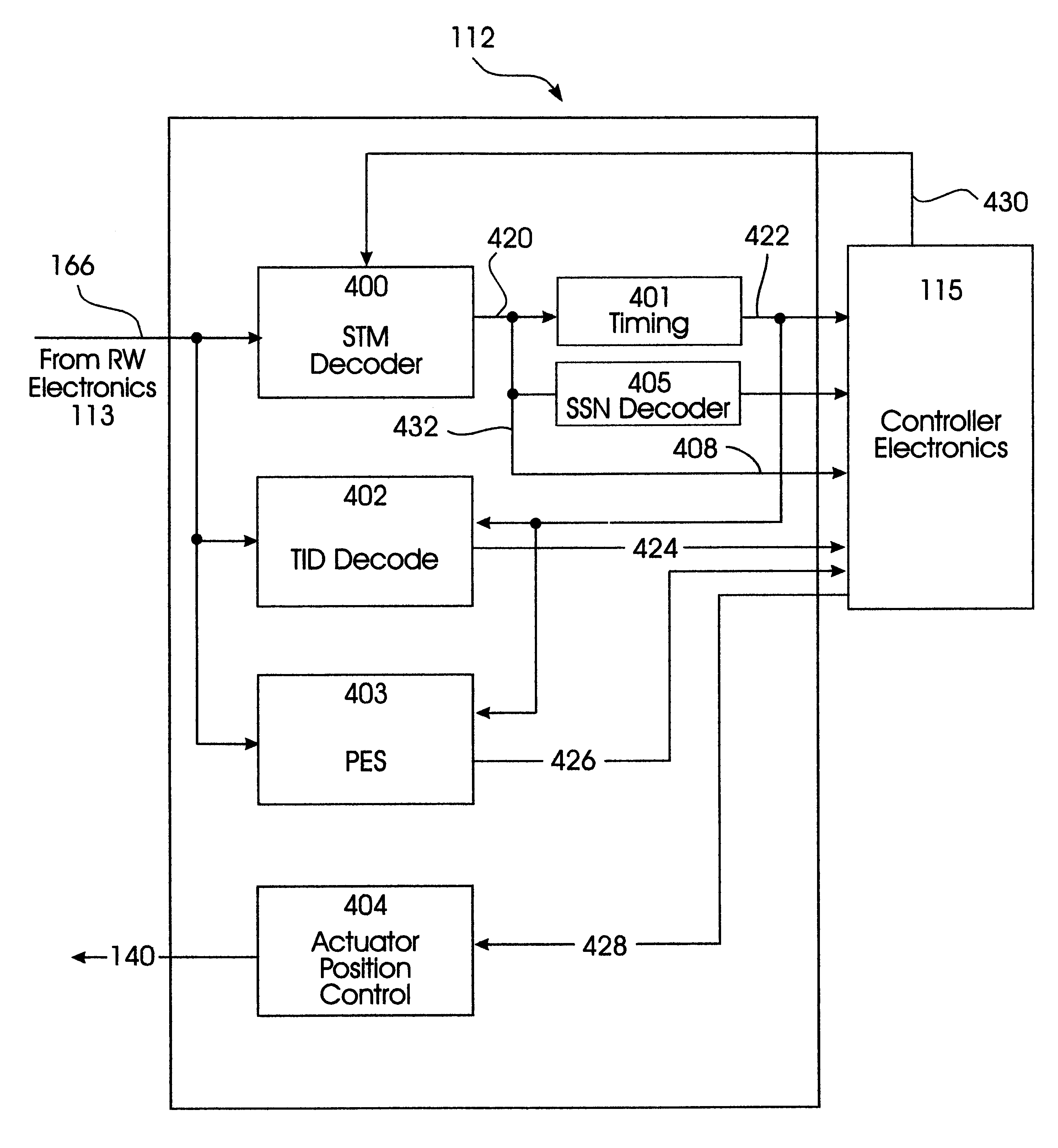
Operation of the Servo System With the STMs

The present invention encodes the SSN onto the disk without impacting the data storage capacity, and simultaneously greatly enhancing the reliability. In the preferred embodiment the SSNs are encoded in a distributed manner through the use of multiple servo types encoded in the STMs in a specific sequence.

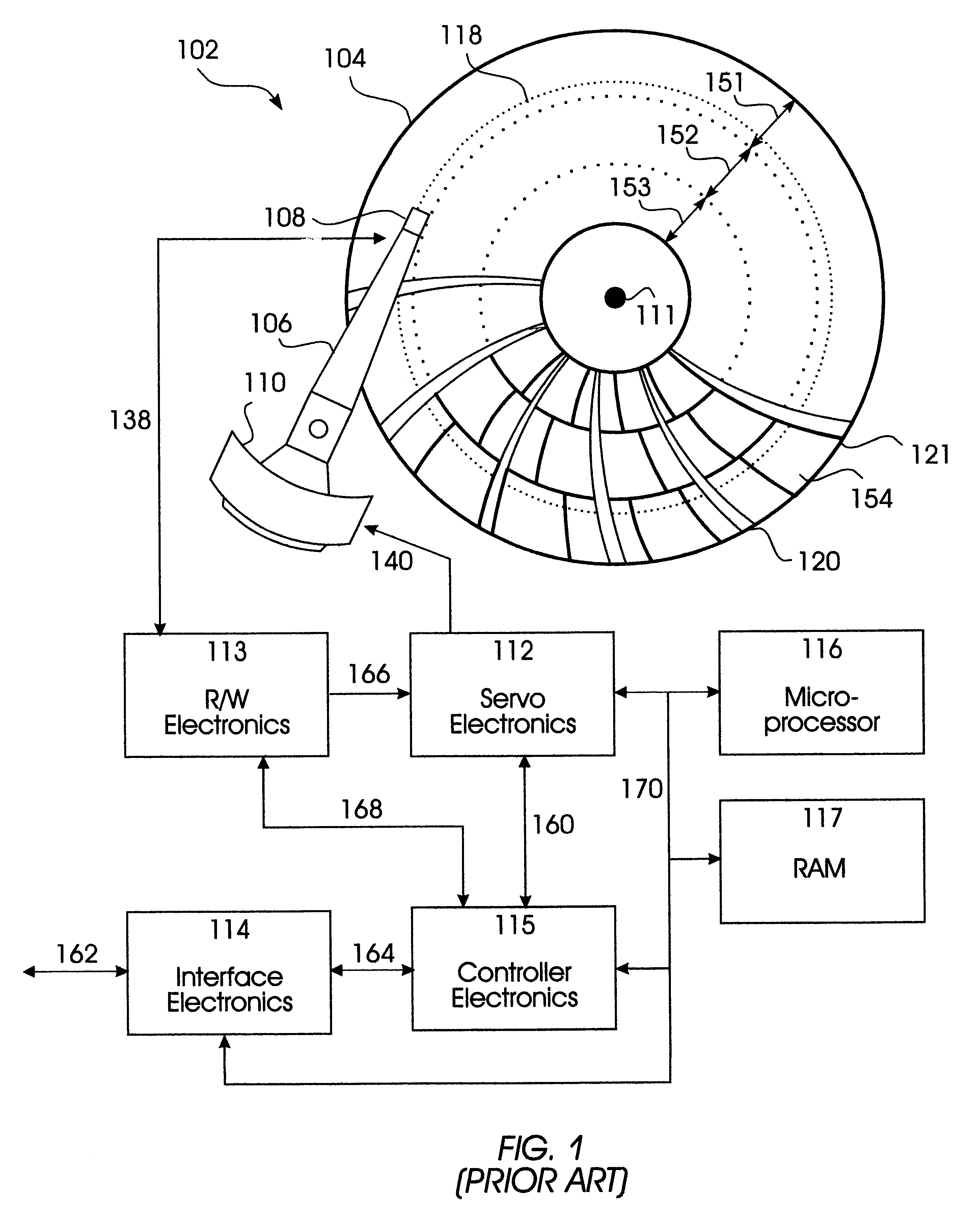
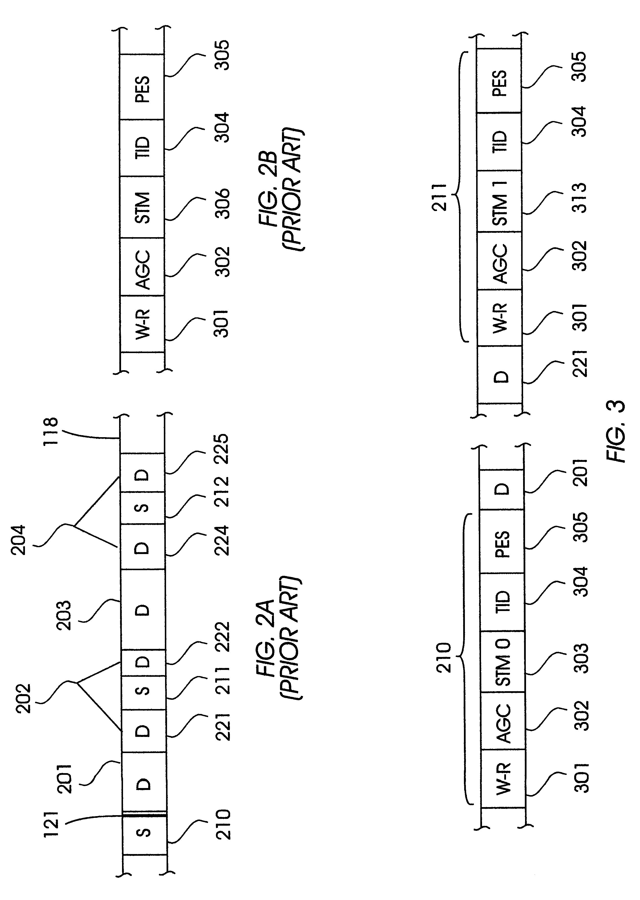
FIG. 3 is a detailed view of a portion of a data track, such as the data track 118 depicted in FIG. 2A, illustrating the contents of the two servo sectors 210 and 211, which are identical except that each contains a different one of the two types of STMs which represent two servo types that are used to encode SSNs according to the present invention.

The servo sector 210 includes a write-to-read recovery (W-R) field 301, a servo sector preamble pattern shown as field 302, a servo timing mark STM0303, track identification (TID) field 304 and position error signal (PES) field 305. The W-R field 301 provides time for the recording system to swi...


PUM

PropertyMeasurementUnit
sliding distanceaaaaaaaaaa
magneticaaaaaaaaaa
lengthaaaaaaaaaa

Abstract

A magnetic recording disk drive has head positioning servo sectors with servo sector numbers (SSNs) that are not recorded on the disk. The SSNs are encoded through the use of multiple servo sector types that are arranged in a specific sequence around the data tracks. The different servo sector types are identified by unique types of servo timing marks (STMs), which are used to locate the servo sectors. The SSNs that are used to identify the servo sectors on the track form a set or code of m fixed n-bit patterns. A SSN is determined when the STM types read from n sequential servo sectors match one of the fixed SSN pattems. A set or code of m servo sectors, where each servo sector is identified by a unique SSN pattern having length n, is denoted as an (m,n,d) code, where d is referred to as the minimum Hamming distance of the code. The Hamming distance between two patterns refers to the number of locations that are different between the two pattems.

Description

This invention relates to disk drives that store recorded digital data, and in particular to disk drives that use servo sectors for maintaining the recording heads on the data tracks during read and write operations.Magnetic recording disk drives incorporate stacked, commonly-rotated rigid magnetic recording disks that are used for storage of user data. The data is recorded in radially-spaced data tracks on the surfaces of the disks. Recording heads are moved by an actuator in a generally radial path toward and away from the center of rotation of the disks to read and write data on the disks. Typically, a single recording head, which may be an inductive read / write head or an inductive write head in combination with a magnetoresistive read head, is associated with a corresponding magnetic recording surface of each disk.It is necessary to know the precise radial and circumferential location of the recording heads relative to their associated disk surfaces. Radial position information ...

Claims


Application Information

Patent Timeline
Patent Type & Authority Patents(United States)
IPC IPC(8): G11B20/18G11B27/30G11B5/596H03M13/00H03M13/47G11B5/55
CPCG11B5/59655H03M13/47G11B27/3027G11B20/18G11B5/553G11B2220/20
Inventor BLAUM, MARIOHETZLER, STEVEN R.KABELAC, WILLIAM JOHN
Owner IBM CORP
Why Eureka
Try Eureka