

Converter circuit arrangement having a DC intermediate circuit
a technology of converter circuit and intermediate circuit, applied in circuit arrangements, power conversion systems, electric power transfer ac networks, etc., can solve problems such as undesirable, but unavoidable, oscillation being excited, and current reaching a considerable amplitude, and achieve undesirable, but unavoidable effects
- Summary
- Abstract
- Description
- Claims
- Application Information
AI Technical Summary
Benefits of technology
Problems solved by technology
Method used
Image

Examples
Embodiment Construction
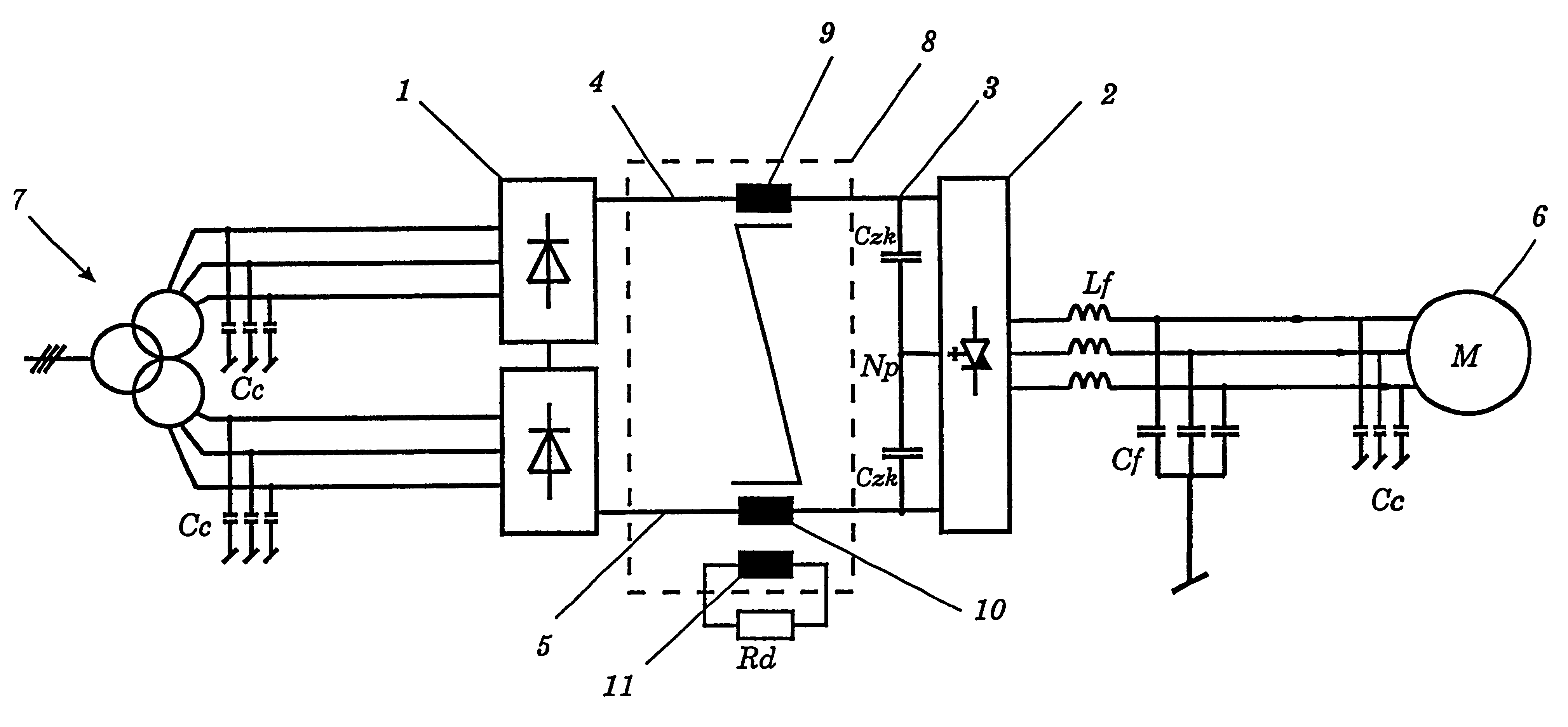
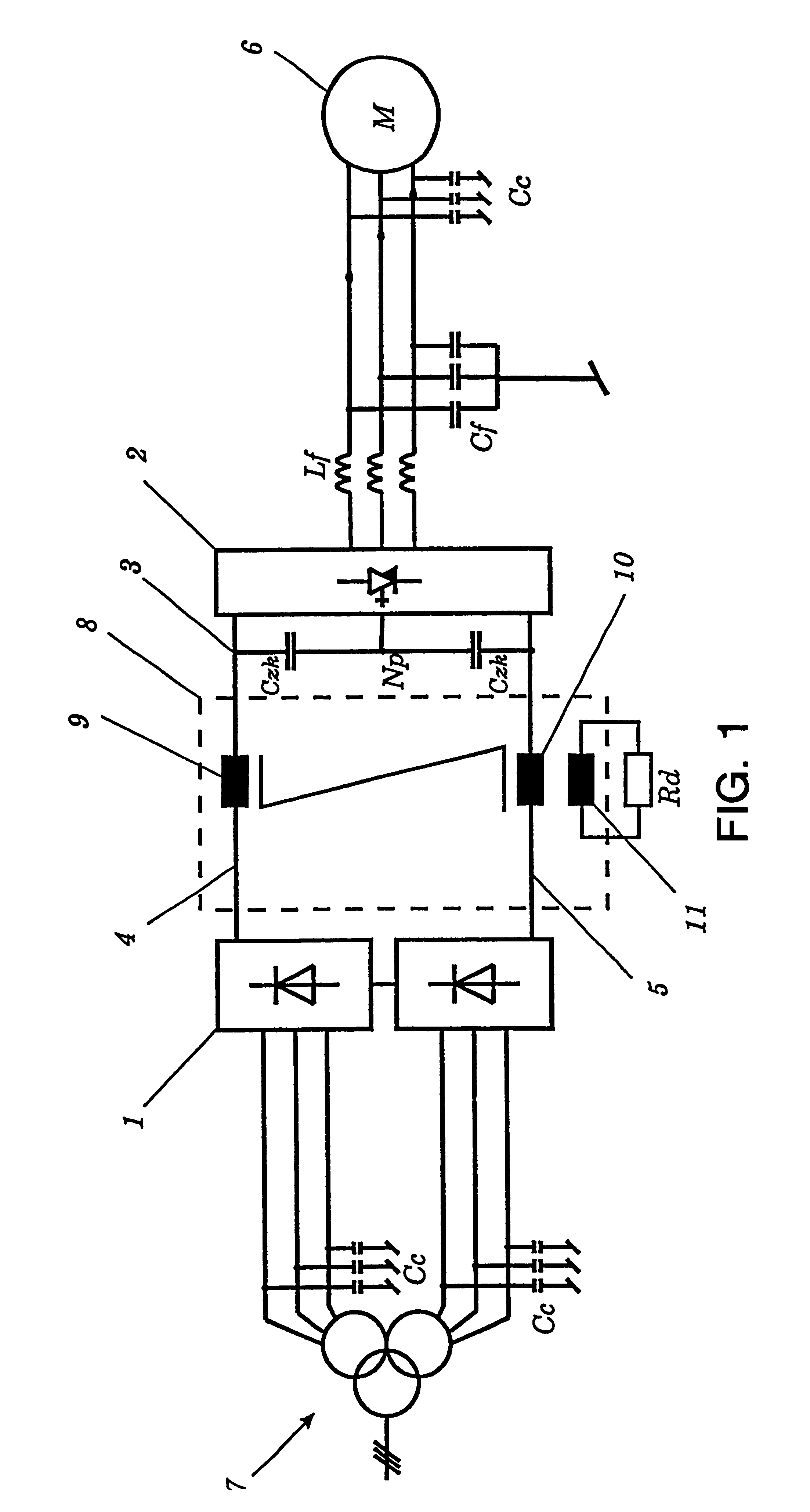
Referring now to the drawings, wherein like reference numerals designate identical or corresponding parts throughout the several views, one exemplary embodiment of the invention is shown schematically in FIG. 1. 7 denotes a three-phase voltage supply network which is connected via a mains transformer to a first converter 1. The three-phase shielded connecting cables form cable inductances and cable capacitances Cc, which are not shown. The AC voltage of the voltage supply network 7 is converted into DC voltage in the converter 1. A DC intermediate circuit 3 comprises intermediate circuit capacitors Czk, which are connected to a positive path 4 and to a negative path 5. The intermediate circuit 3 is connected to a second converter 2, which converts the DC voltage back to an AC voltage of variable frequency and amplitude.
In the exemplary embodiment shown, the second converter 2 is a three-point inverter. In consequence, two series-connected intermediate circuit capacitors Czk are also...
PUM
 Abstract
Description
Claims
Application Information