Helium leak tester for vehicle fuel tanks

a technology for leak testing and fuel tanks, applied in the field of leak testing, can solve the problems of inability to accurately detect leaks, limited leak detection capability of the test equipment described, and obsolete test equipmen

Inactive Publication Date: 2001-09-18
AUTOMOTIVE COMPONENTS HOLDINGS
View PDF30 Cites 39 Cited by
  • Summary
  • Abstract
  • Description
  • Claims
  • Application Information

AI Technical Summary

Problems solved by technology

The test equipment just described is limited in ability to detect leaks smaller than a certain size.
For example, it is believed that the equipment may be incapable of accurately sensing leaks smaller than an equivalent leak that correlates with a hydrocarbon emission leak rate of 100 mg / day.
Increasingly stringent regulations may render that test equipment obsolete for determining fuel tank compliance, not necessarily because of a total inability of the equipment to detect the even smaller leaks, but because the ability to do so will require longer test times and more helium.
Those factors, or the alternative of adding more test machines of the same kind, add cost to the testing of mass-produced vehicle fuel tanks.
It is believed that limitations in the ability of the existing test to efficiently measure even smaller leaks are due to one or more factors, such as an inherent limit in the sensitivity of the mass spectrometer used in the equipment, the amount of time and helium required to charge a tank that is to be tested, and leakage between the chamber space and its ambient surroundings when the hood is closed.
Because the test enclosure comprises a hood that seals against a base, any imperfection in sealing between them may become a source of error in test measurement, possibly even giving a false indication of a leak if residual helium in the ambient surroundings were to intrude into the chamber due to faulty sealing of the closed hood to the base.

Method used


Image

  • Helium leak tester for vehicle fuel tanks
  • Helium leak tester for vehicle fuel tanks
  • Helium leak tester for vehicle fuel tanks

Examples


Embodiment Construction

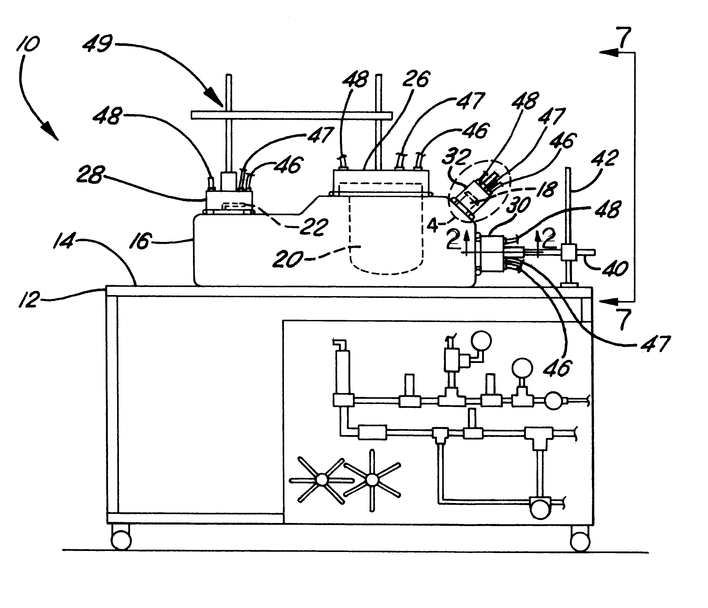
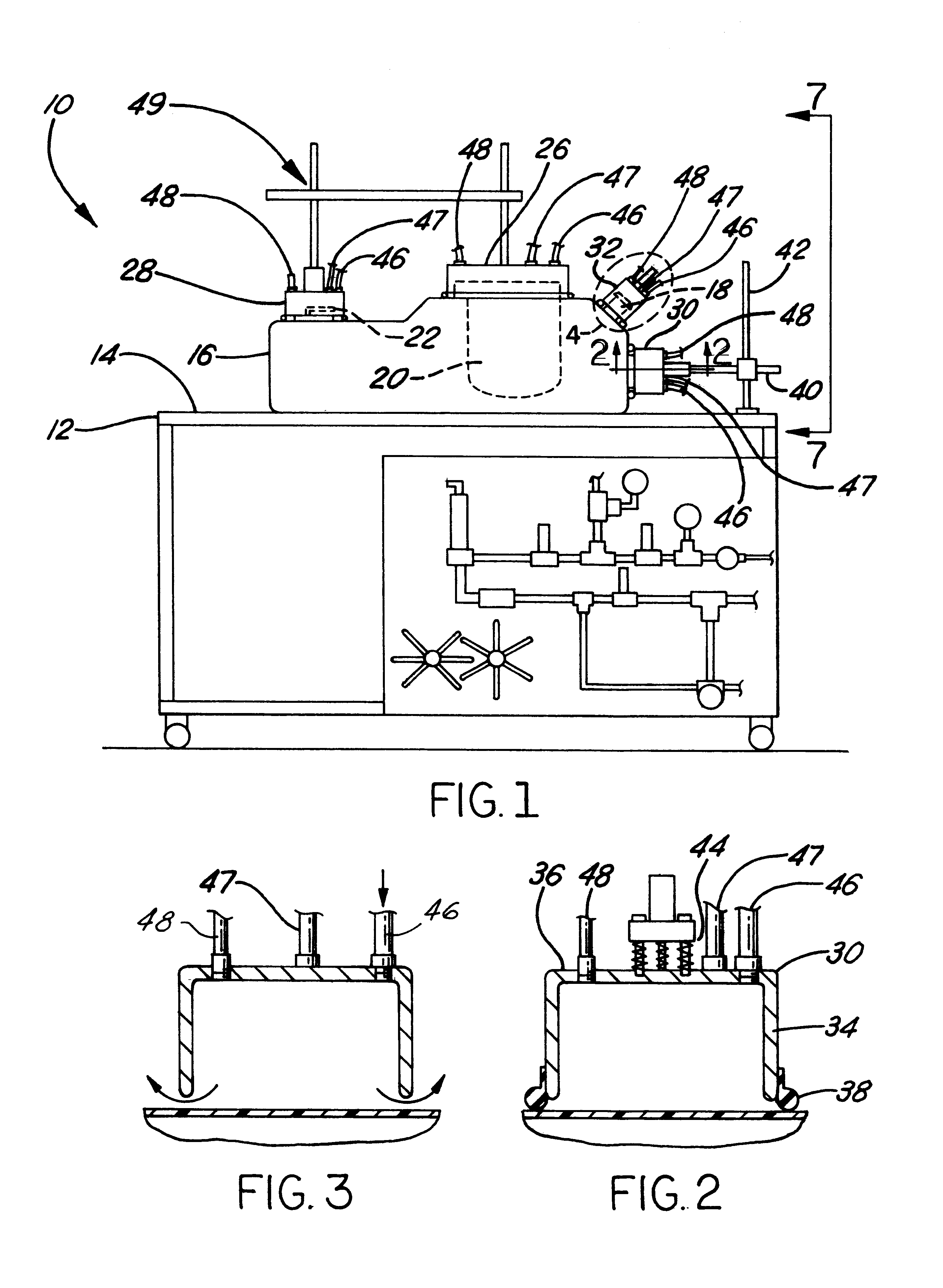
FIG. 1 shows an exemplary embodiment of leak detection test equipment 10 according to principles of the present invention. A stand 12 provides a horizontal top surface 14 on which a fuel tank 16, which is representative of tanks that can be tested in accordance with principles of the present invention, has been placed for testing. Tank 16 is fabricated by using known methods and apparatus to mold suitable material, polymeric material for example, to the desired shape. The tank typically has multiple openings in its wall that serve different purposes. One opening near a corner of a top wall of the tank contains a fill spud 18 through which liquid fuel can enter the tank interior when the tank is in an automotive vehicle and being filled with a supply of fuel for an engine that powers the vehicle. A fuel pump module 20 may be mounted in closure of another opening in the top wall of the tank. Another device 22, such a vent valve for example, may be mounted in closure of still another o...


PUM


Abstract

A method of leak testing a walled tank (16) that has multiple joints containing closures or closure devices (18, 20, 22, 24) closing openings in the wall. Rims (38) of multiple cups (26, 28, 30, 32) are disposed against the tank wall to place the cup interiors in substantial sealed covering relation to underlying zones of the tank wall containing joints to be checked. A tank seal (52) is disposed fluid-tight against a fill spud (18) in the tank wall, and a test gas, helium, is introduced into the interior of the tank. Gas from within the interior of each cup is sampled via a respective sampling conduit (48), and a purge gas is introduced into the interior of each cup via a respective purge conduit (46) while the gas from the interior of each cup is being sampled via the respective sampling conduit.

Description

1. Field of the InventionThis invention relates to leak testing that uses a test gas, and more particularly to leak testing of an automotive vehicle fuel tank before it is installed in a vehicle using helium as the test gas.2. Background InformationOne type of equipment that is in use for leak testing mass-produced automotive fuel vehicle tanks before they are installed in a vehicle comprises a test chamber having a hood that opens to allow a fuel tank to be placed within a test chamber space, that then closes during the test, and that finally re-opens after the test to allow the tested fuel tank to be removed. After the hood closes, helium is introduced into the interior of the fuel tank in a manner that achieves sufficient helium concentration and pressure within the tank for the test to proceed. The helium is introduced into the tank through an opening in the tank wall, such as a fill spud, via a conduit that terminates in an end fitting that associates with the tank opening in a...

Claims


Application Information

Patent Timeline
Patent Type & Authority Patents(United States)
IPC IPC(8): G01M3/22G01M3/20G01M3/02
CPCG01M3/226G01M3/025
Inventor LYCAN, PAUL DALESCHELLENBERG, AARON THOMAS
Owner AUTOMOTIVE COMPONENTS HOLDINGS
Why Eureka
Try Eureka