Wildlife guard cover

a technology for wildlife guards and covers, applied in the direction of insulated conductors, cables, conductors, etc., can solve the problems of frequent short circuits and consequent power outages, service interruptions that are undesirable for both customers and electrical utilities, and manufacturing facilities with sensitive processes often cannot tolerate even momentary power interruptions

Inactive Publication Date: 2001-09-18
RELIANT ENERGY
View PDF22 Cites 89 Cited by
  • Summary
  • Abstract
  • Description
  • Claims
  • Application Information

AI Technical Summary

Benefits of technology

The entry slots are of a size allowing a range of locations of entry of the wire to accommodate a variety of field conditions. The entry slots are also located in the wall members on opposite sides of the cover to permit electrical pass-through or zero length connections and yet allow the guard to be installed without improvisation and removed without damage to it.
The wildlife guards of the present invention are provided with a new and improved lock or closure mechanism. The lock mechanism includes a flexible, resilient member which flexes to allow closure and opening of the protective wildlife cover. The lock mechanism is such that, when the wildlife cover is in the closed position, the cover is locked closed, but the flexible, resilient member is in a relaxed, stress-free state. Thus, even in cold weather, when the insulating cover material becomes more brittle, the lock mechanism remains viable and the protective purpose of the cover is maintained. The lock mechanisms of the present invention are such that the flexible, resilient members of each lock flex toward one another, thus allowing a line crew member to open the cover with two fingers of a single hand, thus allowing the opening of the cover with a minimum of effort and time. The cover is also preserved for future use. The wildlife guards are thus easy to be installed and removed by a line crew member.
The wildlife guards of the present invention are also provided with bottom wall or closure members which can be easily fitted to a variety of insulative bushing sizes. Thus the wildlife guards of the present invention can be adapted to accommodate a range of insulative bushing skirts of various outer diameters and inner core diameters, as well. The wildlife guards of the present invention are also provided with a resilient yieldable central top opening to allow an incoming conductor to pass into the cover for connection. Further, top portions of the wildlife guard are made easily removable to allow conductors, fuses or other equipment of various sized to be connected within the cover.

Problems solved by technology

If such contact occurred, short circuits and consequent power outages frequently were the result.
Service interruptions are undesirable to both customers and the electrical utility.
Even momentary service interruptions are a nuisance for customers because they have required customers to reset digital clocks and other such devices.
For utilities, service interruptions have required field service personnel to replace blown fuses and to repair or replace damaged equipment.
For example, a circuit breaker in a substation and thus for an entire circuit might operate and hundreds of customers could have service interrupted as a result of a single wildlife-caused short circuit.
Manufacturing facilities with sensitive processes often cannot tolerate even momentary power interruptions.
However, there have been several problems with these types of enclosures.
Without the air gaps, leakage currents on the contaminated surfaces of the arresters will cause spurious sparkovers of many arresters and this can cause many arresters to fail prematurely.
Unfortunately, field conditions vary widely and the sparkgap bar locations with respect to the electrical equipment bushing geometry could often vary widely.
Unfortunately, bending the sparkgap bar increases the air gap distance which increases the sparkover voltage which can cause failure of the protected equipment.
Also, the covers might later work loose and leave the electrical connection exposed.
If the temporary makeshift measures became ineffective, the wildlife protective function for which the covers were intended was thus defeated.
At times during usage, it also may have been necessary to remove the wildlife protective cover once installed.
Unfortunately, the lock mechanisms of previous cover designs keep lock mechanism parts under mechanical stress.
This frequently has caused the lock mechanisms to break over time, especially in cold weather conditions where the cover material normally becomes more brittle.
A number of the presently available cover type housings were difficult to remove.
The covers did not have lock release mechanisms and were difficult to grasp once installed because the bottom opening of the cover was often inaccessible between insulator skirts.
For this reason, large amounts of effort were often required to open the locking mechanism.
In addition, if at times too much force was exerted, cover locking mechanism would be broken on opening it.
This rendered the wildlife cover unsuitable for further use.
Since the protective cover wildlife guards were typically hinged, this presented a problem.
The conductors could not be installed through the pivotable sidewalls of the cover, since the sidewalls needed to move in order to close the cover in place when installed.
The hinges thus made installation of covers difficult in these situations.
Unfortunately, this failed to accommodate the range of inner diameter or cores.
However, the strength and structural integrity of the cover suffered in the areas where flexibility was offered to accommodate some bushing sizes where the inner diameter or core was only slightly less than the outer skirt diameter.
In these cases, the flexible portions were too large and would permit the cover to come loose from its insulative bushing and again defeat the wildlife protective purpose of the cover.
Furthermore, the inner opening of the flexible bottom closure wall was frequently too small for the bushing core diameter to allow closure of the cover around the bushing.

Method used


Image

  • Wildlife guard cover
  • Wildlife guard cover
  • Wildlife guard cover

Examples


Embodiment Construction

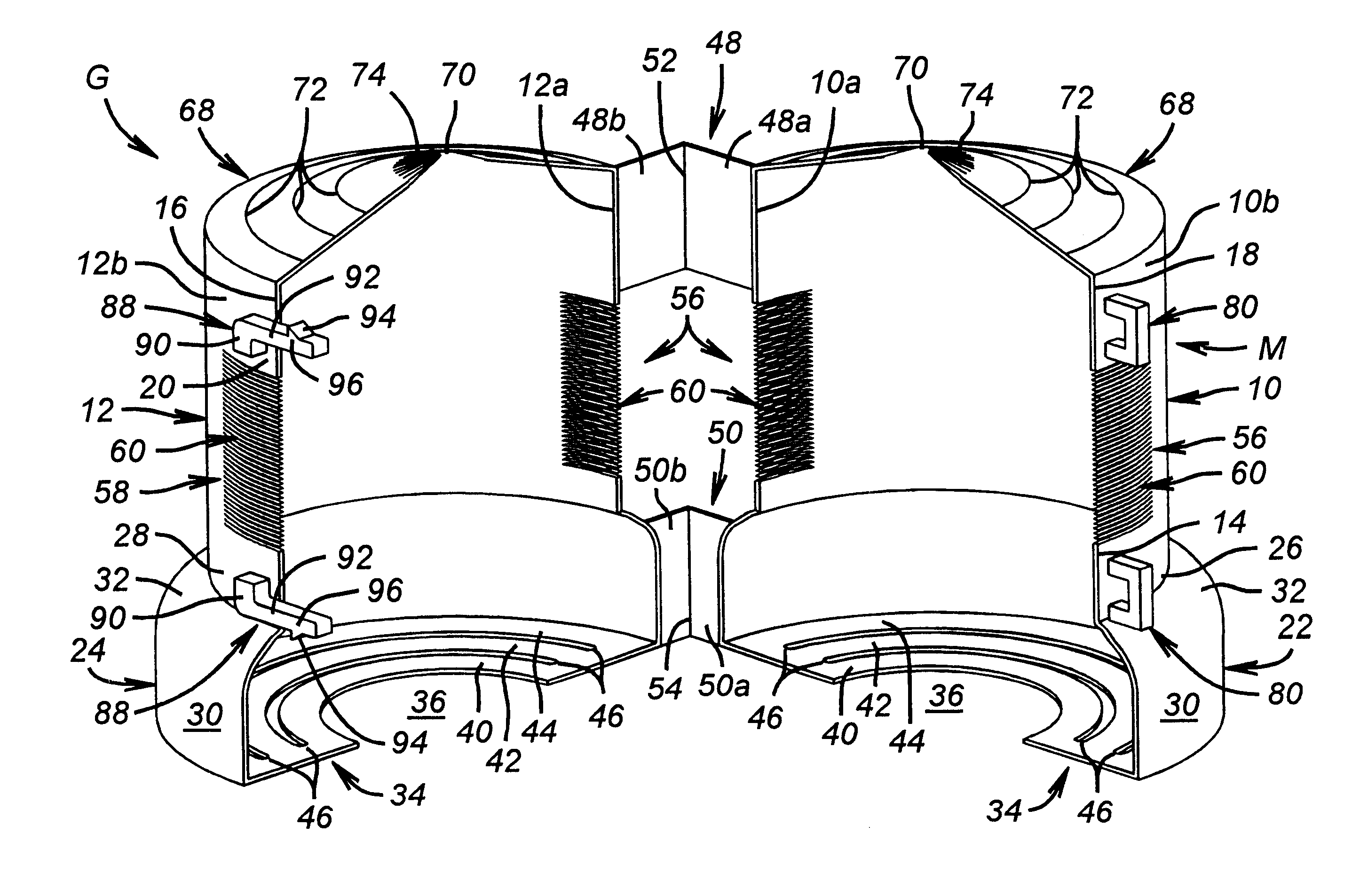
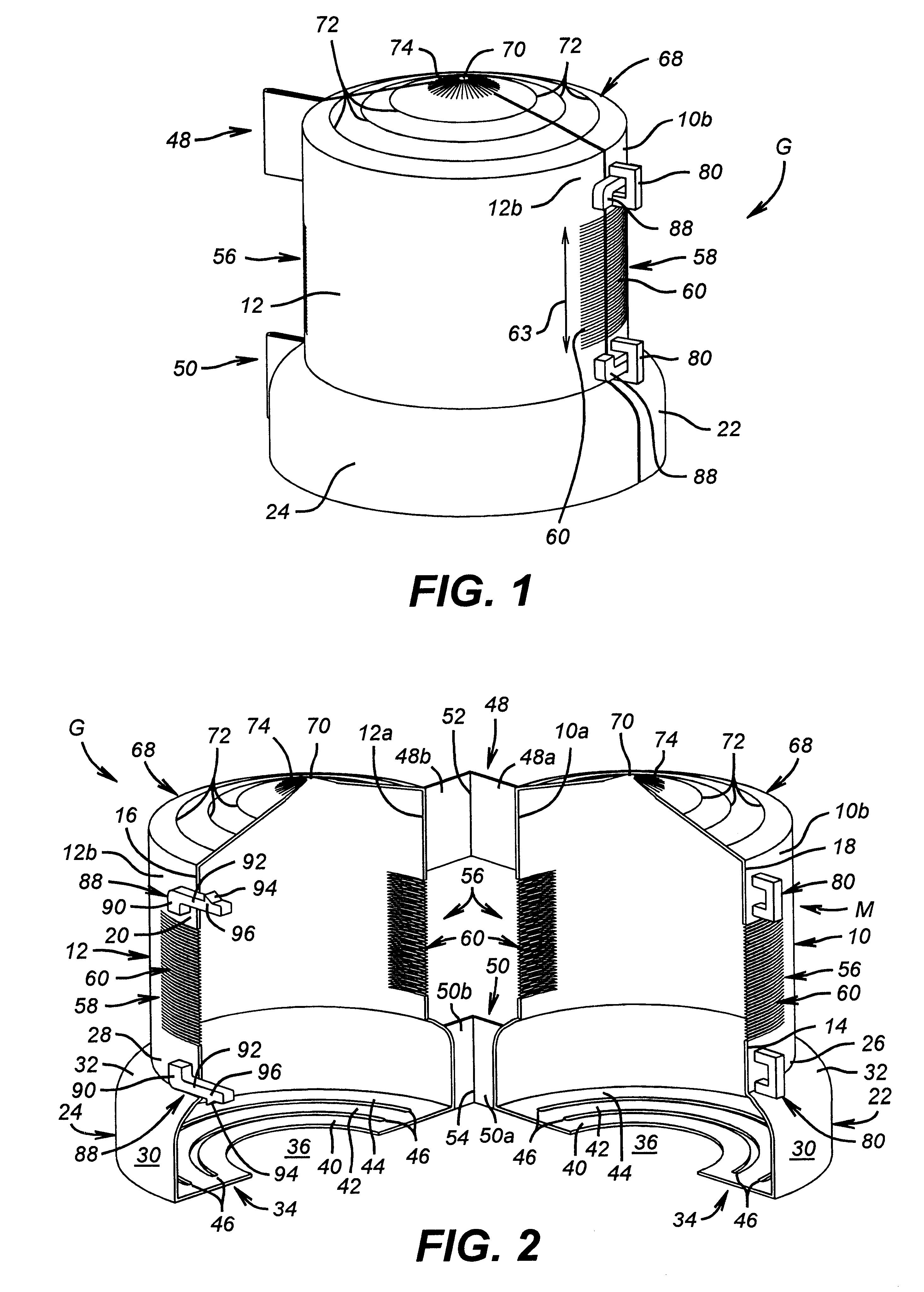
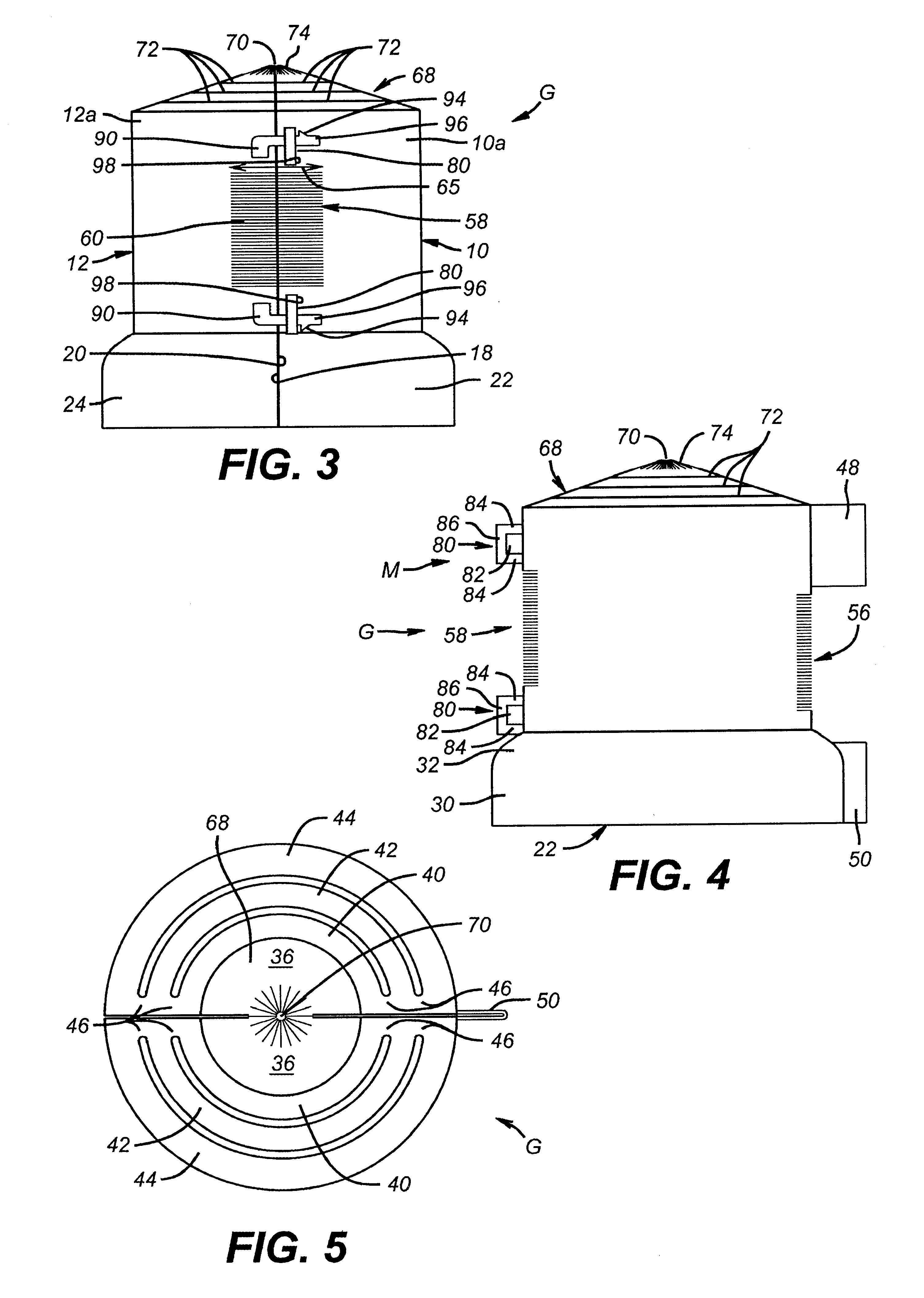
In the drawings, the letter G designates generally a wildlife guard for enclosing a connection to electrical power distribution equipment. The electrical power distribution equipment may be any of numerous forms, including transformers and lightning arresters. Thus, the wildlife guard of the present invention may be installed at locations such as on an insulative arrester bushing A (FIG. 6) on a lightning arrester or an insulated transformer bushing B (FIGS. 7-9) on a power distribution transformer. Typically, different ones of these bushings have different diameters at outer skirt portions S and inner core portions C.

The wildlife guard G is typically formed as an integrally molded unitary piece of a suitable insulative synthetic resin, such as UV stabilized polypropylene. The wildlife guard G includes a first generally cylindrical wall member 10 and a second generally cylindrical wall member 12. The wall members 10 and 12 are generally half-cylinders, having mating contact surfaces...


PUM

PropertyMeasurementUnit
thicknessaaaaaaaaaa
cross-sectional widthaaaaaaaaaa

Abstract

A wildlife guard for electrical power distribution equipment has two hingedly mounted sections which close together to form a protective cover at the top of an insulator bushing on electrical equipment. The wildlife guard is adapted by its structure to fit a range of bushing sizes and yet provide structural integrity and reliable protection once in place. The wildlife guard also accommodates passage of conductive members such as electrical conductors and sparkgap bars through the cover at locations governed by actual field conditions. The wildlife guard has a cover locking mechanism allowing its easy removal when desired.

Description

SPECIFICATION1. Field of the InventionThe present invention relates to protective wildlife guards for electrical power distribution equipment.2. Description of the Related ArtDistribution equipment used to supply electrical power has used wildlife protection guards or covers to prevent wildlife from simultaneously contacting energized and grounded surfaces. If such contact occurred, short circuits and consequent power outages frequently were the result. Service interruptions are undesirable to both customers and the electrical utility. Even momentary service interruptions are a nuisance for customers because they have required customers to reset digital clocks and other such devices. For utilities, service interruptions have required field service personnel to replace blown fuses and to repair or replace damaged equipment. For example, a circuit breaker in a substation and thus for an entire circuit might operate and hundreds of customers could have service interrupted as a result o...

Claims


Application Information

Patent Timeline
Patent Type & Authority Patents(United States)
IPC IPC(8): H01B17/00
CPCH01B17/00
Inventor WILLIAMS, RICHARD BRENT
Owner RELIANT ENERGY
Why Eureka
Try Eureka