
Radiating coaxial cable having groups of spaced apertures for generating a surface wave at a low frequencies and a combination of surface and radiated waves at higher frequencies

a coaxial cable and surface wave technology, applied in waveguides, slot antennas, antennas, etc., can solve the problems of increasing the potential of water moving through the apertures and into the cable, increasing the insertion loss, and increasing the coupling loss. , to achieve the effect of minimizing the number of apertures, minimizing the potential of water moving through the apertures and low coupling loss

Inactive Publication Date: 2001-09-18
TIMES MICROWAVE SYST DIV OF SMITHS AEROSPACE
View PDF13 Cites 21 Cited by
  • Summary
  • Abstract
  • Description
  • Claims
  • Application Information

AI Technical Summary

Benefits of technology

An advantage of the present invention is that the radiating coaxial cable exhibits low coupling loss over a wide frequency band.
is that the radiating coaxial cable exhibits low coupling loss over a wide frequency band.
Another advantage of the present invention is that the radiating coaxial cable minimizes the number of apertures defined in its outer conductor in order to minimize the potential of water migrating into the inside of the cable and to obtain an acceptable insertion loss for internal TEM waves.

Problems solved by technology

The coupling loss also increases with increasing frequency.
The number of apertures per cable length is therefore high, thus increasing the insertion loss and increasing the potential of moisture migrating through the apertures and into the cable.
This design generates a surface wave below the radiating operational frequency band, but a high coupling loss limits its use at those frequencies.

Method used


Image

  • Radiating coaxial cable having groups of spaced apertures for generating a surface wave at a low frequencies and a combination of surface and radiated waves at higher frequencies
  • Radiating coaxial cable having groups of spaced apertures for generating a surface wave at a low frequencies and a combination of surface and radiated waves at higher frequencies
  • Radiating coaxial cable having groups of spaced apertures for generating a surface wave at a low frequencies and a combination of surface and radiated waves at higher frequencies

Examples


Embodiment Construction

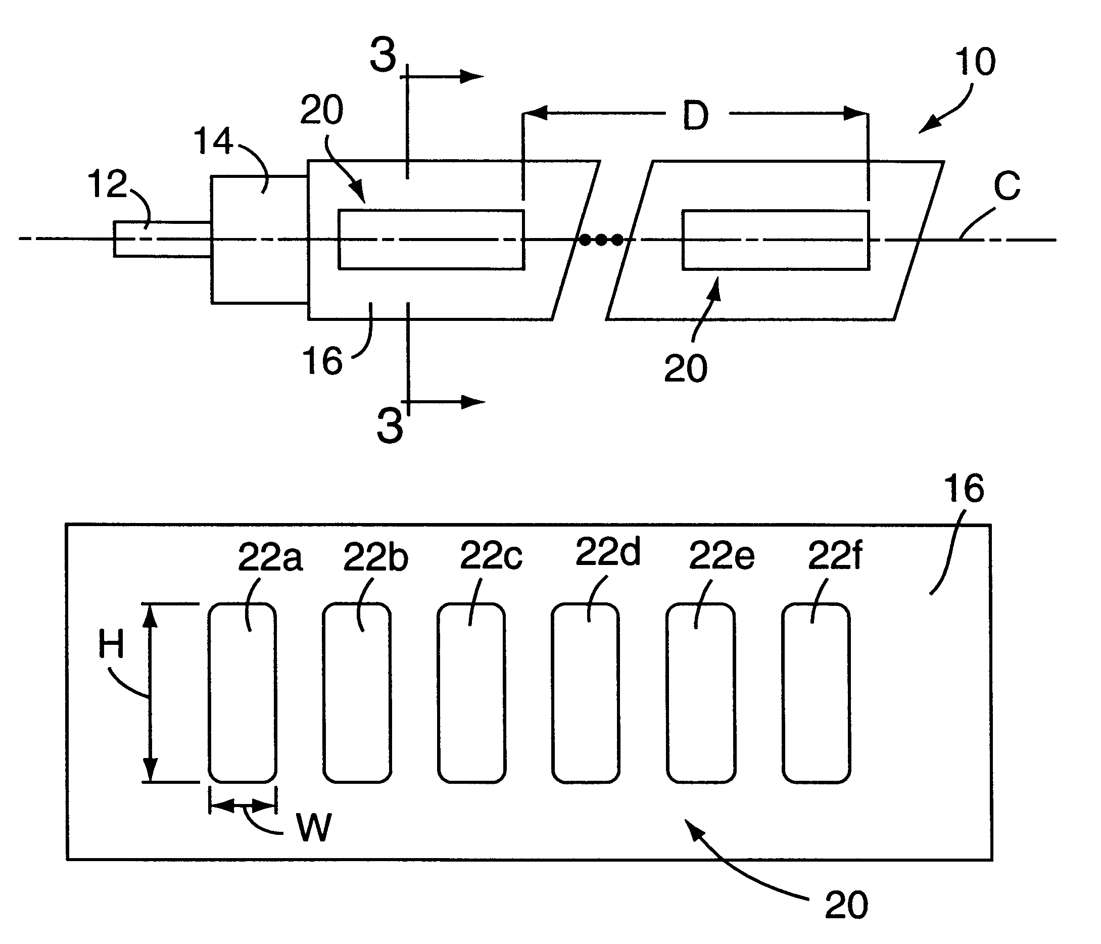
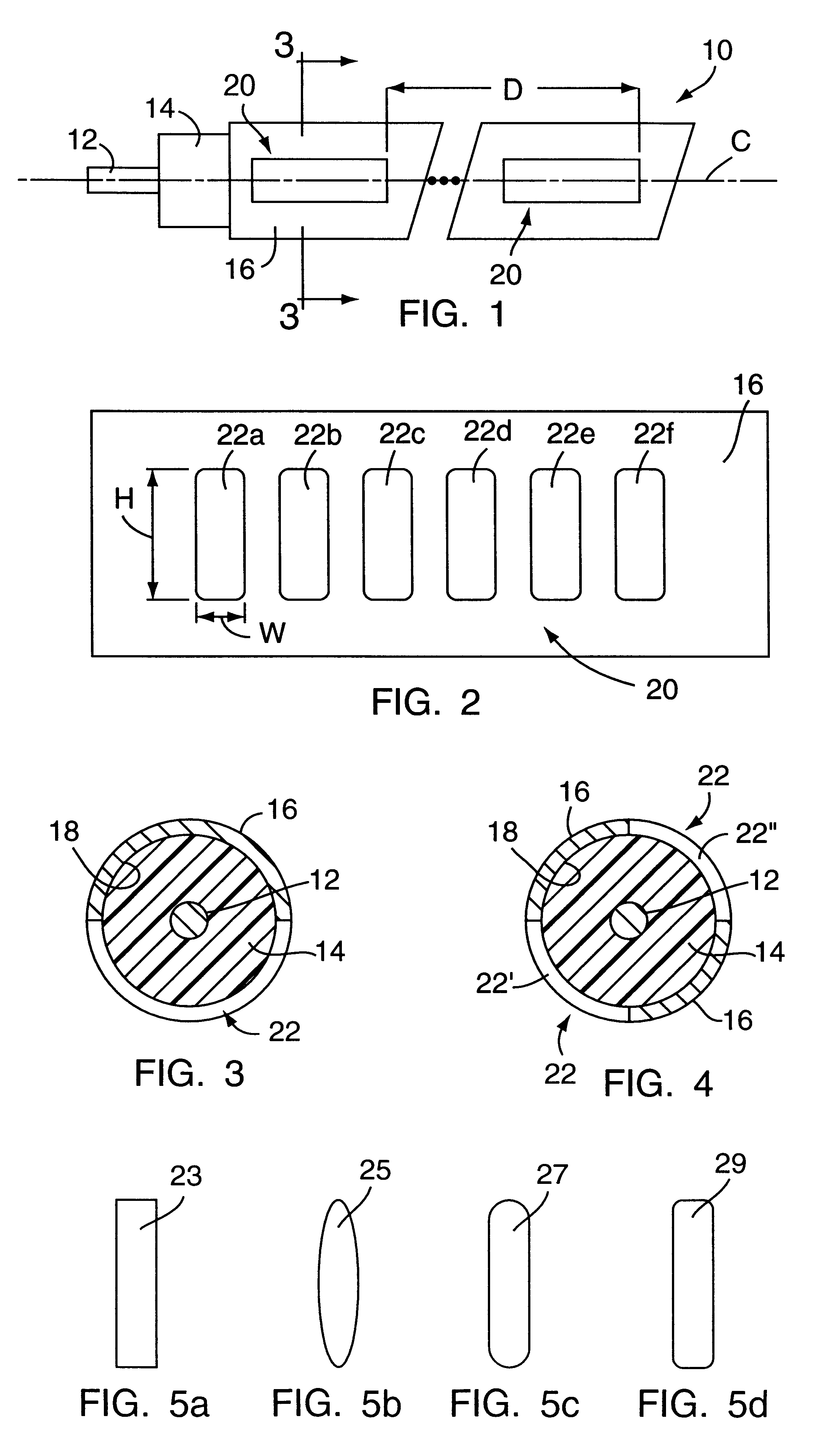
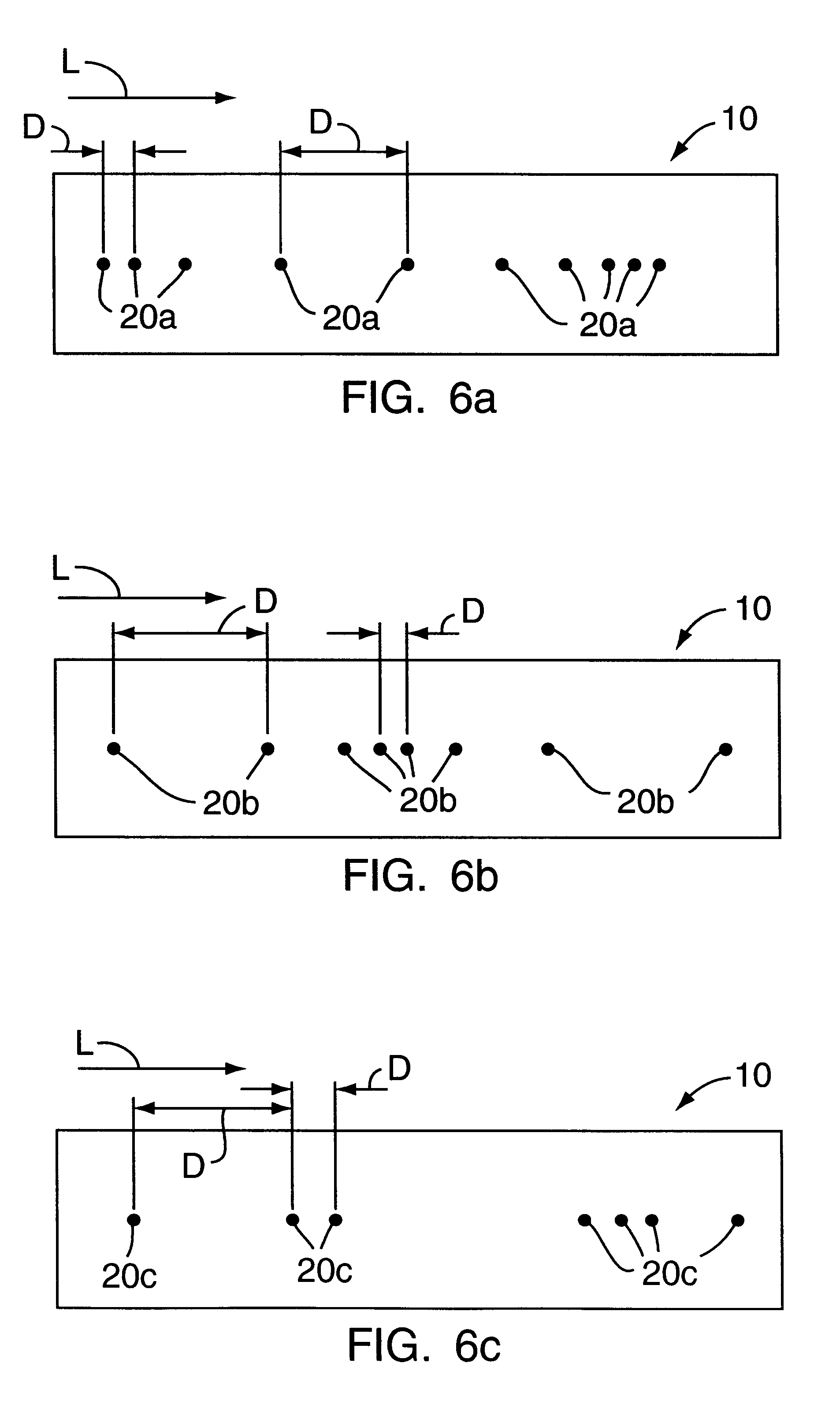
Radio frequency (RF) and microwave frequency electromagnetic waves are transmitted through a coaxial cable in the form of a transverse electromagnetic (TEM) wave. Groups of openings in the outer conductor are used to transfer energy to the outside of the cable. This energy forms mainly a surface wave (Goubau wave) for low operational frequencies (i.e., RF frequencies) and a combination of surface wave and radiated wave for high operational frequencies (i.e., microwave frequencies). The combination of surface wave and radiated wave at high operational frequencies substantially lowers the coupling loss, and does not limit the operational frequency bandwidth of the radiated coaxial cable.

With reference to FIGS. 1-5, a leaky / radiating coaxial cable embodying the present invention is generally designated by the reference number 10 (FIG. 1). For simplicity of illustration, the outer protective jacket of the coaxial cable 10 is not shown. The coaxial cable 10 comprises a solid or hollow in...


PUM


Abstract

A radiating coaxial cable includes an inner conductor, an electrical insulator located about a periphery of the inner conductor, and an outer conductor located about a periphery of the electrical insulator. The outer conductor defines groups of apertures spaced from each other a predetermined distance in the range of from about twice the longest operational wavelength of the cable to less than ten meters. The aperture groups are designed in such a way to excite a surface wave at low operating frequencies and a combination of surface and radiating waves at high operational frequencies.

Description

FIELD OF THE INVENTIONThe present invention relates generally to a radiating coaxial cable, and more particularly to a radiating coaxial cable having groups of spaced apertures for generating a surface wave at low frequencies and a combination of surface and radiated waves at higher frequencies.BACKGROUND OF THE INVENTIONRadiating and leaky coaxial cables are employed as longitudinal antennas in confined spaces like tunnels, mines, buildings and in other stretched-out applications involving a narrow lateral corridor needed for one or two way communication, such as railroads and highways.Leaky coaxial cables support surface waves. The coupling loss between cable and antenna increases proportionally as 1 / r.sup.2, where r is the distance between the cable and the antenna. The coupling loss also increases with increasing frequency. Leaky coaxial cables are known to employ, for example, outer conductors defining equally spaced groups of apertures, longitudinal apertures, corrugated outer...

Claims


Application Information

Patent Timeline
Patent Type & Authority Patents(United States)
IPC IPC(8): H01Q13/20
CPCH01Q13/203
Inventor BODE, UDO H.FEDOR, ANTHONY R.
Owner TIMES MICROWAVE SYST DIV OF SMITHS AEROSPACE
Learn More