Camera support including extendable post

a technology of camera support and extendable post, which is applied in the direction of machine support, cable arrangement between relatively moving parts, instruments, etc., can solve the problems of more time-consuming operations, time-consuming, and cost of components owned in duplicate, so as to avoid clearance problems and lens height variations, and maintain dynamic balan

Inactive Publication Date: 2001-09-25
BROWN GARRETT W
View PDF18 Cites 56 Cited by
  • Summary
  • Abstract
  • Description
  • Claims
  • Application Information

AI Technical Summary

Benefits of technology

It is also an object of the present invention to provide a novel structure for a telescoping post, with means for appropriate gimbal placement and positioning of counterbalancing masses so that it can be statically and dynamically balanced with any combination of post length and selected camera, monitor, and battery weights; and still provide a useable monitor viewing position.
It is also an object of the present invention to provide a tilting head attached between the camera and the centerpost to independently tilt the camera from the orientation of the centerpost, in order to help maintain dynamic balance when the Steadicam.RTM. pans around the vertical axis of the said centerpost, with the lens axis at an angle other than horizontal.
It is a further object of the invention to provide a tilting head to independently tilt the camera from the orientation of the centerpost in order to avoid clearance problems and lens height variations caused by tilting the entire Steadicam.RTM. sled.
It is also an object of the invention to provide a practical and novel camera tilting head between the camera and the centerpost support, which is small and compact, and which, when functioned, does not cause an unacceptable shift in the camera's c.g. and does not obstruct the region of the top of the said post, so that both normal and extended-post operation can be accomplished with the said post maintained more closely in a vertical position.
It is a further object of the invention to provide a novel method and device to permit the retraction of internal electrical wiring without fouling even when the oversized telescoping is fully shortened.

Problems solved by technology

In the intervening years, a number of problems and new opportunities have been identified, which have not yet been resolved or facilitated by existing Steadicam.RTM. equipment.
The problem with this arrangement is the time it takes to switch over from the conventional Steadicam.RTM. camera stabilizer configuration, and the cost of the components that are owned in duplicate in order to prevent even more time-consuming operations.
In order to make this changeover, operators must presently disconnect and remove the camera, disassemble the sled, reassemble, re-install, reconnect, etc., and the result is that operators and their clients dread the time taken to change over to (and back from) ultra high-mode or ultra low-mode shooting.
Also, because of its enormous length, the "super-post" mode makes it impossible to achieve the most common range of lens heights, which are between the knees and head of the operator.
A further difficulty with existing super-post designs is that even the stiffest carbon-fiber post designs are prone to vibration and "whipping" during high-speed running, violent maneuvers, or shots made while riding in bumpy vehicles.
Problems have also arisen with existing super-post designs, because, with light cameras and corresponding lower gimbal positions (the gimbal needs to be at the center of gravity), the range of monitor positions providing an acceptable line of sight for the operator is severely restricted.
There is another mode of shooting that has always been problematic.
These kinds of shots can be dangerous when carrying the 70+ pounds of the conventional Steadicam.RTM. rig with all accessories.
However, according to today's most common usage, a large number of ancillary components must also be duplicated and mounted for this purpose, such as a remote video transmitter so the director can watch the shot in progress, and additional wireless focus-pulling equipment so that the camera assistant can adjust the focus of the lens.
Like most Steadicam rigs, the Master Series rig comes with an expandable post, but its range is severely limited because of the need for the sled to be at a normal size for most shooting.
This is a useful feature, but constraints of the present configuration of the sled mean that the amount of travel of monitor and battery is quite limited.
Available Steadicam.RTM. designs do not provide for independent tilting of the camera.
This has required the whole "sled" (the entire camera support structure) to be tilted, causing a number of problems.
This becomes meaningless and counterproductive, when the sled centerpost is not held vertical, since panning now requires this axis to artificially precess around true vertical.
In addition, maintaining this perpetual tilt frequently causes physical interference when operators "switch" the equipment from one side of the body to the other, since such a move is more likely to be obstructed by the Steadicam.RTM. arm hardware when the sled is tilted down and its lower components are therefore displaced to the rear.
Of course this also exacerbates the clearance problems encountered when moving through tilt quarters on a set because the post now sticks out considerably, both in front of and behind the operator.
One reason that tilting heads have not been devised previously for Steadicam.RTM. is that use of known designs would tend to cause additional problems.
The functioning, for example, of conventional tripod-head-type tilt mechanisms would cause violent changes in the position of the camera's center of gravity, thus requiring elaborate rebalancing.
ost. Also, such designs, insofar as is known, would all require excessive size and weight in order to provide for as much as 20.degree. of tilt up and
down. Their excessive depth would restrict the range of gimbal positions near the top of the post which are employed to balance the heavier ca
meras. Also, such conventional tilt heads would obstruct access to any clamps or hardware positioned high on the post just below the
Another problem, even with previous small telescoping posts is getting the internal electrical wires to retract without fouling when the posts are fully shortened.

Method used


Image

  • Camera support including extendable post
  • Camera support including extendable post
  • Camera support including extendable post

Examples


Embodiment Construction

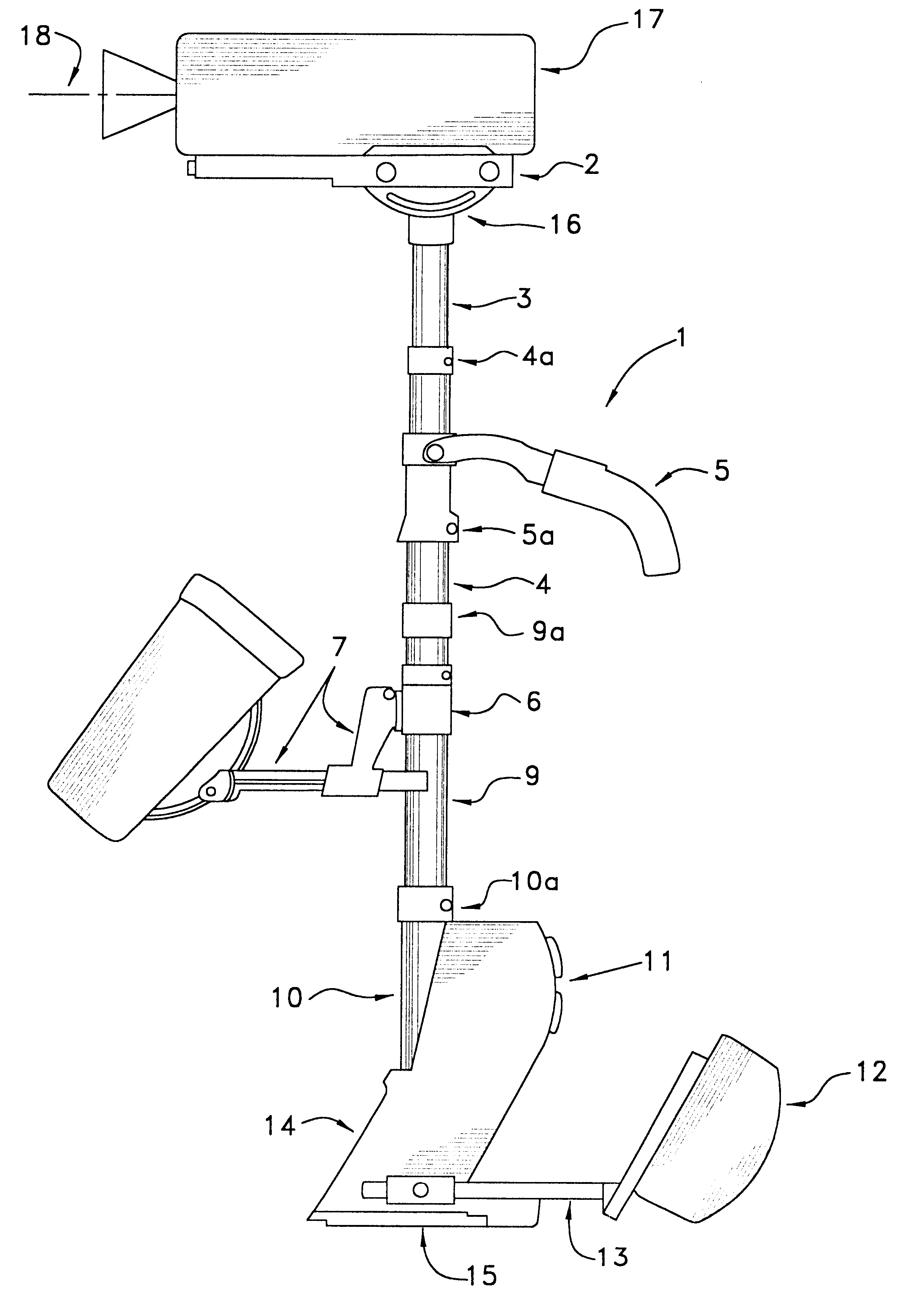
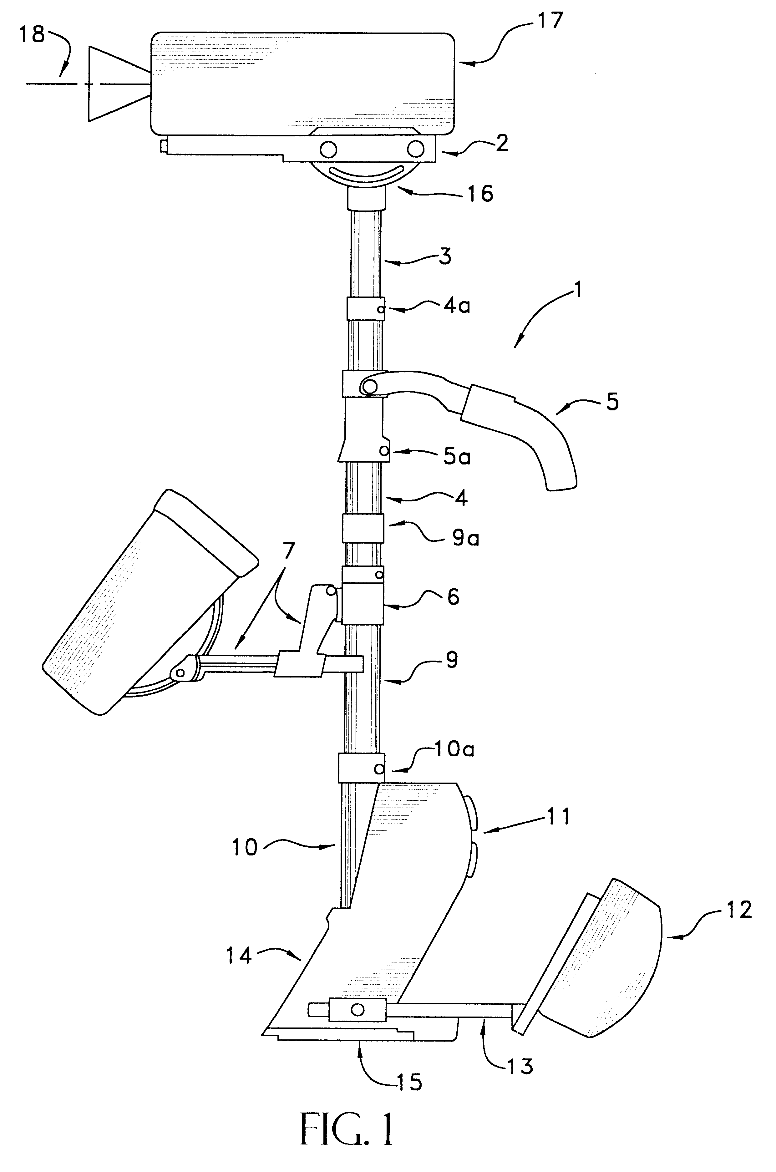
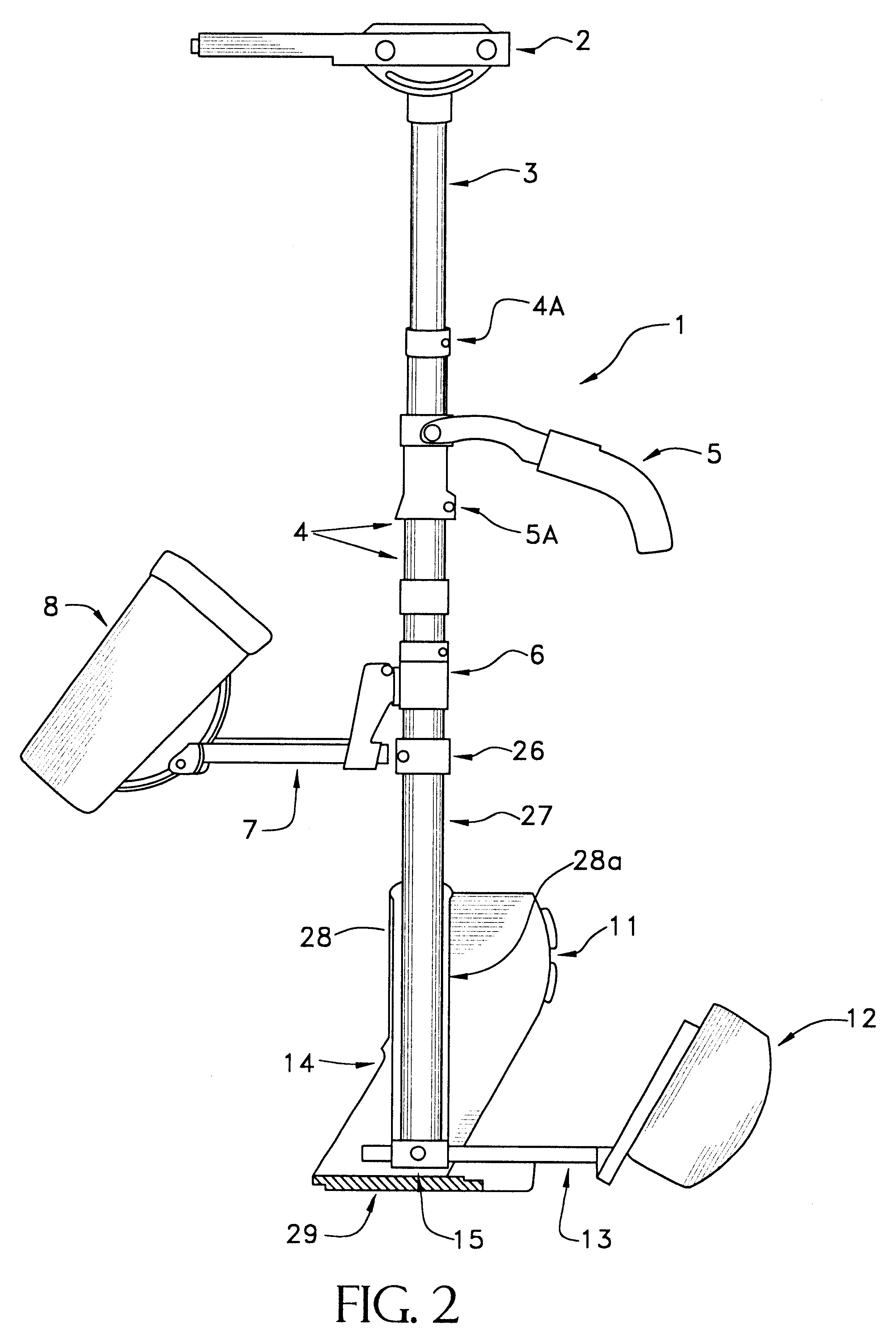
A preferred embodiment comprises a novel structure for a telescoping post as follows: A main section adapted to provide an unobstructed range of positions for gimbal and monitor bracket placement, at least one additional telescoping section of lesser diameter between this main section and the camera mounting, and at least another additional telescoping section between the main section and the mounting for the counterbalancing equipment, such as the battery. The telescoping post includes monitor and battery mountings adapted to be positioned at varying perpendicular distances from the post. The structure is therefore adapted to be balanced statically and dynamically throughout the entire range of possible post lengths, and with any combination of selected camera, monitor, and / or battery weights. As used herein the term camera refers to any sensing or imaging device or any means for capturing an image or information. As used herein the monitor refers to any viewable display, viewing m...


PUM


Abstract

For extended long-post operation of a Steadicam(R)-type camera stabilizer while retaining static and dynamic balance throughout the entire range of post sizes and various component weights, the present invention is directed to an arrangement of telescoping posts, component positioning hardware, electrical wire retracting hardware, and optional hardware to augment rigidity.

Description

The Steadicam.RTM. camera stabilizer has become a mainstay of the motion picture and video industries (see U.S. Pat. Nos. Re. 32,213; 4,017,168; 4,156,512; 4,208,028; 4,474,439; 5,360,196; 5,435,515; and 5,579,071, the teachings of which are incorporated herein by reference). The camera stabilizer comprises an expanded camera support (i.e., the "sled"), an operator vest, and an articulated equipoising arm that is attached between the vest and a three-axis gimbal on the camera support. The Steadicam.RTM. camera stabilizer permits a camera operator (carrying a camera) to walk, run, climb stairs, etc., while maintaining a stable image. It received an Oscar for Scientific / Technical Achievement in 1978. In the intervening years, a number of problems and new opportunities have been identified, which have not yet been resolved or facilitated by existing Steadicam.RTM. equipment.Since 1979, operators have routinely operated the Steadicam.RTM. camera stabilizer with the sled inverted, so tha...

Claims


Application Information

Patent Timeline
Patent Type & Authority Patents(United States)
IPC IPC(8): F16M13/04F16M11/02F16M11/10H02G11/00
CPCF16M11/10F16M11/2014H02G11/006F16M13/04H02G11/00F16M11/28
Inventor HOLWAY, JERRY
Owner BROWN GARRETT W
Why Eureka
Try Eureka