Method and apparatus for venting a diecasting mould of a diecasing machine

a diecasting machine and diecasting mould technology, which is applied in the direction of foundry moulding apparatus, foundry cores, foundry moulds, etc., can solve the problems of limited maximum venting efficiency, increased cross sectional area of valve and venting channel, and increased mass of the movable parts of the valve assembly. achieve the effect of high venting efficiency

Inactive Publication Date: 2001-10-09
FONDAREX
View PDF3 Cites 15 Cited by
  • Summary
  • Abstract
  • Description
  • Claims
  • Application Information

AI Technical Summary

Benefits of technology

Thus, it is an object of the present invention to propose a method for venting the diecasting mould of a diecasting machine by which a higher venting efficiency can be achieved, still maintaining a reliable operation.
It is a further object of the invention to provide a valve assembly by means of which the method of the invention can be optimally performed.
With the method as outlined above, the venting efficiency can be considerably increased, because the provision of a second venting valve that is closed before the mould cavity is completely filled results in at least a doubling of the mean cross sectional area of the channels relevant for the venting efficiency, whereby simultaneously the venting channel portion leading to the second venting valve can be optimized as far as the flow resistance is concerned.

Problems solved by technology

The maximal venting efficiency is limited particularly by the turns and variations of the cross sectional area in the venting channel because thereby the flow resistance for the gases escaping from the mould cavity is substantially increased.
However, tests conducted with such a design have shown that an increase of the cross sectional area of the valve and the venting channel doesn't offer the desired success because the flow resistance of the venting channel, due to its design full of corners, hinders an efficient venting as was always the case.
An increase of the size of the venting valve, moreover, results in an increase of the mass of the movable parts of the valve assembly.
Thus, consequently, the force required for closing the venting valve increases correspondingly, and / or the closure time of the venting valve increases to an undesired high value.
Moreover, an increase of the cross sectional area of the venting valve and of the venting channel results in the fact that the dimensions of the valve assembly are increased as well; this is also not desired.

Method used


Image

  • Method and apparatus for venting a diecasting mould of a diecasing machine
  • Method and apparatus for venting a diecasting mould of a diecasing machine
  • Method and apparatus for venting a diecasting mould of a diecasing machine

Examples


Embodiment Construction

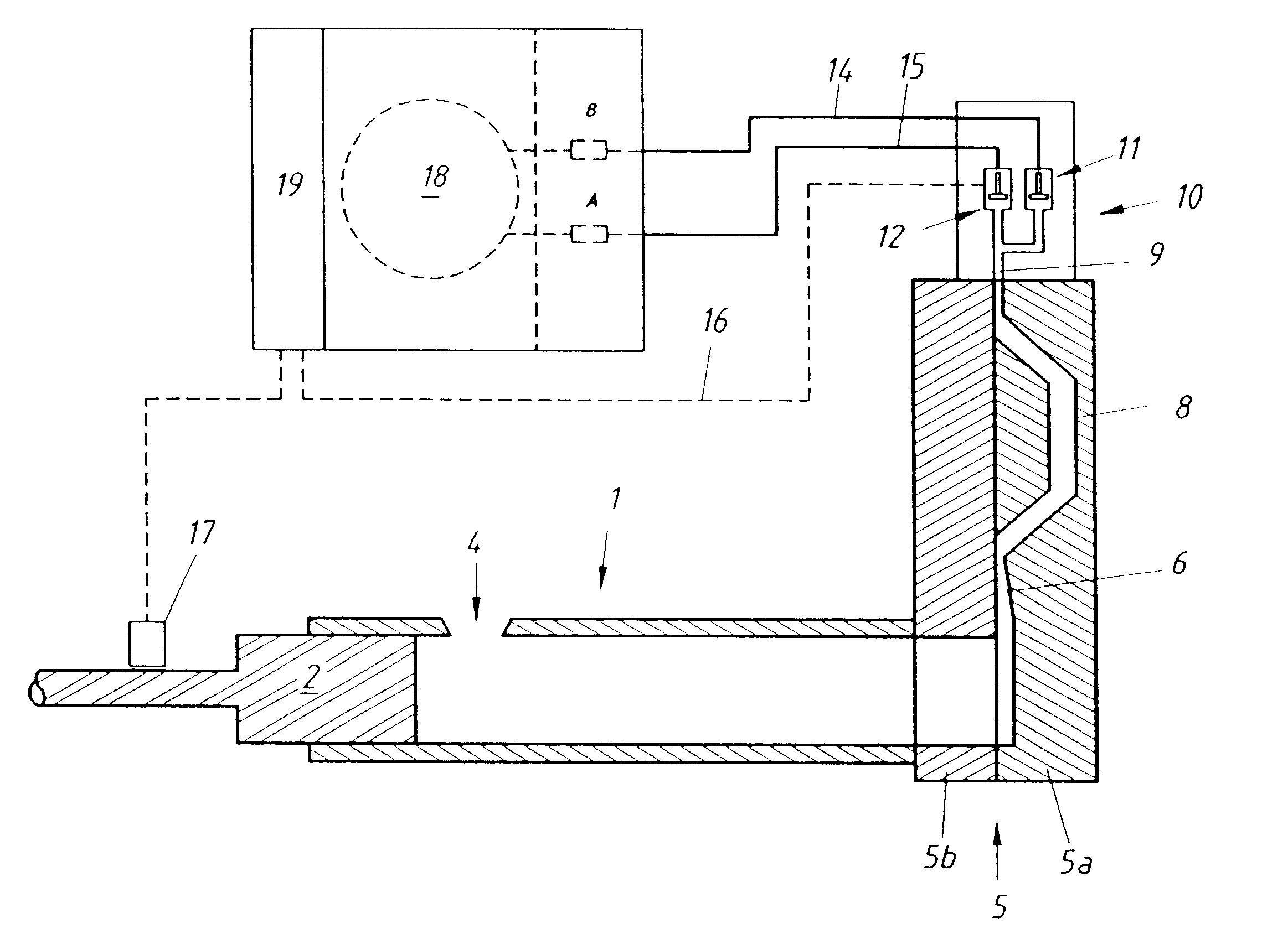
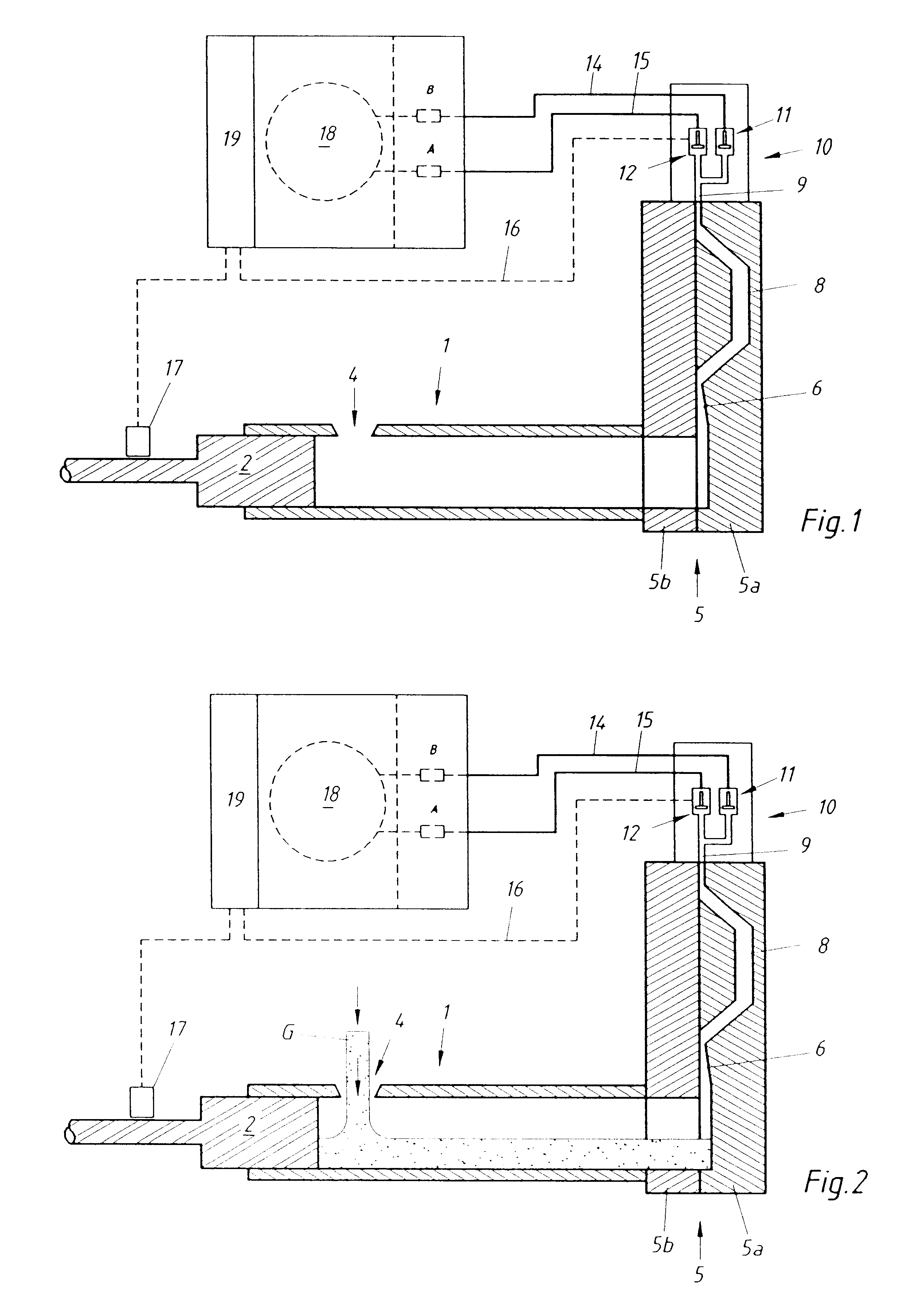
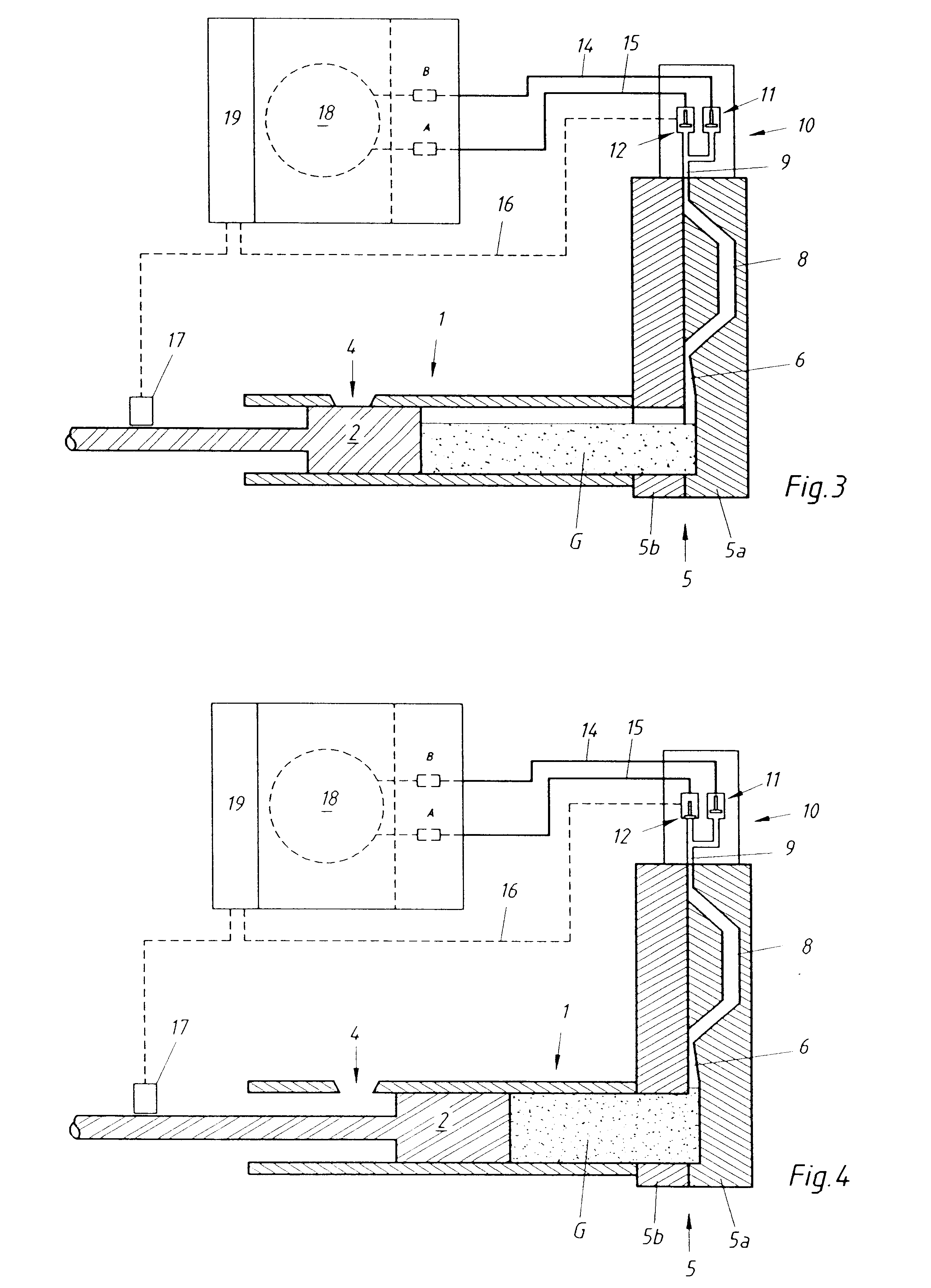
With the aid of FIG. 1, the general design and the general mode of operation of an embodiment of the diecasting machine according to the invention as well as the valve assembly assigned thereto will be further explained, whereby only those characteristics and method steps will be discussed which are essential in connection with the present invention.

As the essential components of the diecasting machine, in the present example, a pressure chamber 1 and a casting piston 2, located in the interior of the pressure chamber 1 and hydraulically driven, are illustrated in FIG. 1. The pressure chamber 1 is provided with a filling aperture 4 for filling the pressure chamber 1 with the liquid casting material. At the outlet end of the pressure chamber 1, a diecasting mould 5 is located which comprises two mould halves 5a and 5b. A connecting channel 6 runs from the pressure chamber 1 to the mould cavity 8 located between the two mould halves 5a and 5b. At the top side of the diecasting mould 5...


PUM

PropertyMeasurementUnit
cross sectional areaaaaaaaaaaa
mean cross sectional areaaaaaaaaaaa
lengthaaaaaaaaaa

Abstract

In order to vent a diecasting mold of a diecasting machine, it is proposed that the mold cavity and / or the pressure chamber are vented during the filling operation by a second venting valve, additionally to a first venting valve. The first venting valve is located in a venting channel portion that communicates with a venting channel leading out of the mold cavity. For operating the first venting valve, an impact transmitter is provided that is operationally connected to the first venting valve and that is exposed to and moved by the casting material advancing from the mold cavity to the venting channel. The second venting valve is operated by separate independent means and is closed before the mold cavity is completely filled. As a criterion for closing the second venting valve, the length of the path can be used along which the casting piston runs during the filling operation.

Description

The present invention refers to a method for venting a diecasting mould of a diecasting machine that is provided with a casting piston located in a pressure chamber and adapted for pressing liquid casting material into a mould cavity of the diecasting mould. The diecasting mould is provided with at least one venting channel communicating with the mould cavity. It comprises a first venting valve operationally connected to an impact transmitter exposed to and moved by the liquid casting material advancing from the mould cavity into the venting channel.Moreover, the present invention refers to a valve assembly for venting a diecasting mould of a diecasting machine that is provided with a casting piston located in a pressure chamber and adapted for pressing liquid casting material into a mould cavity of the diecasting mould, whereby the diecasting mould is provided with a venting channel communicating with the mould cavity.In order to avoid the occurrence of trapped air in the finished ...

Claims


Application Information

Patent Timeline
Patent Type & Authority Patents(United States)
IPC IPC(8): B22D17/00B22D17/14B22D17/22B22C9/00
CPCB22D17/145B22D17/20
Inventor WYSER, JOHANNGUTH, HEINRICH
Owner FONDAREX
Why Eureka
Try Eureka