Optical communication method and optical communication system based on optical phase conjugation
a communication method and optical phase conjugation technology, applied in the field of optical communication methods and optical communication systems, can solve the problems of chromatic dispersion or group velocity dispersion, many problems to be solved in systems, and simple construction of conventional systems
- Summary
- Abstract
- Description
- Claims
- Application Information
AI Technical Summary
Problems solved by technology
Method used
Image
Examples
fourth embodiment
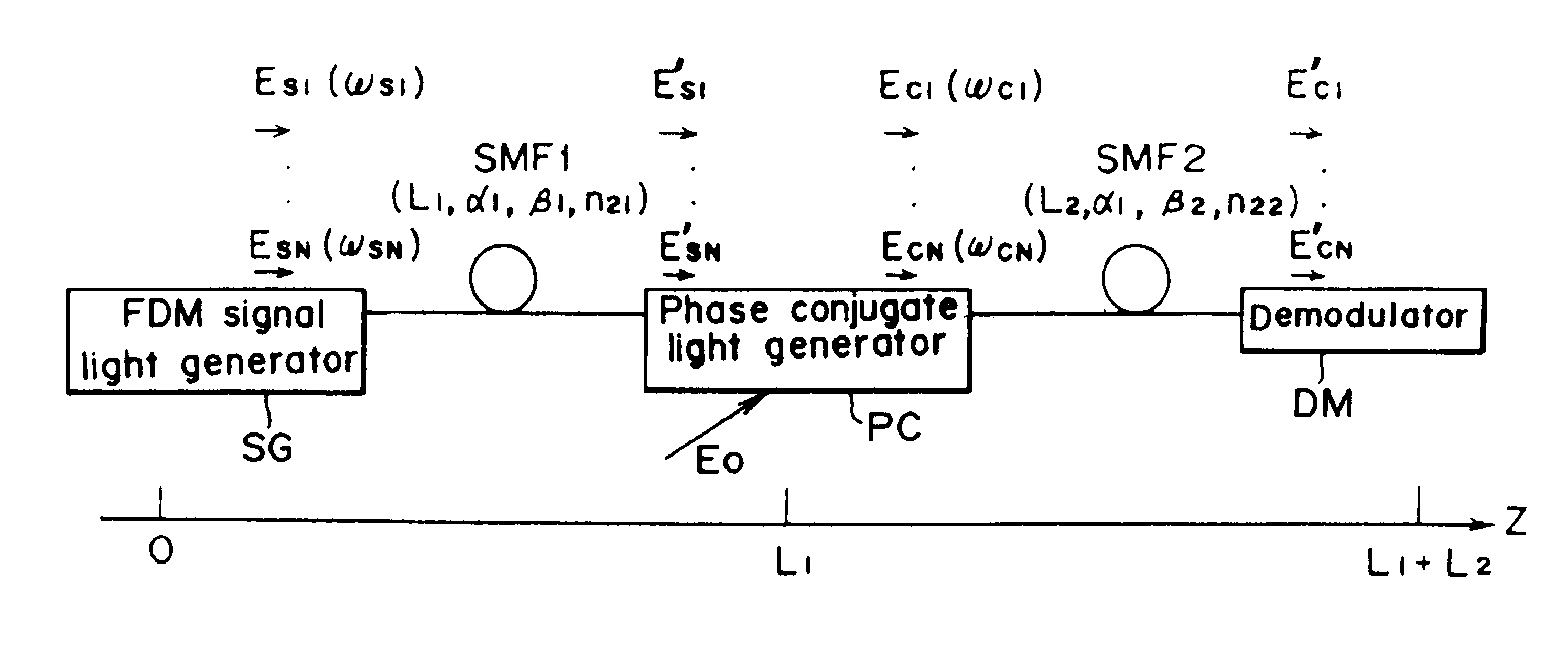
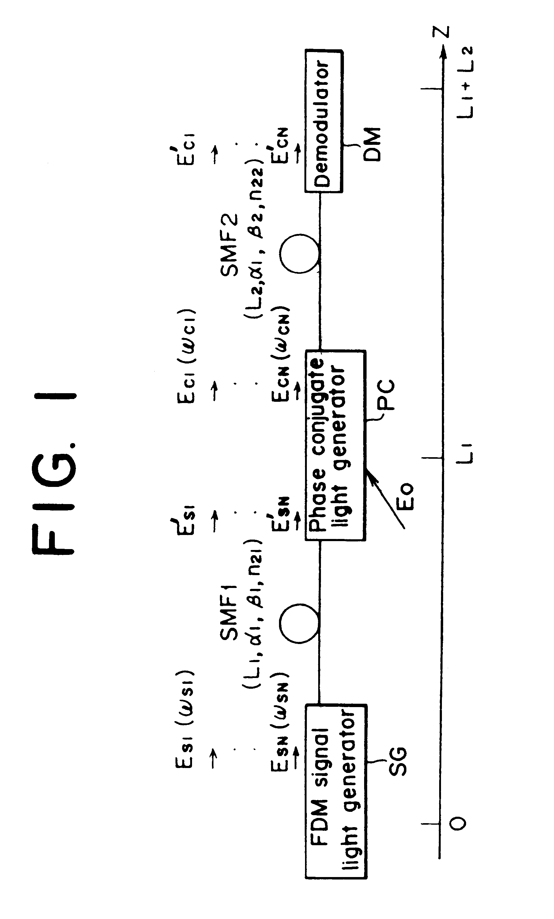
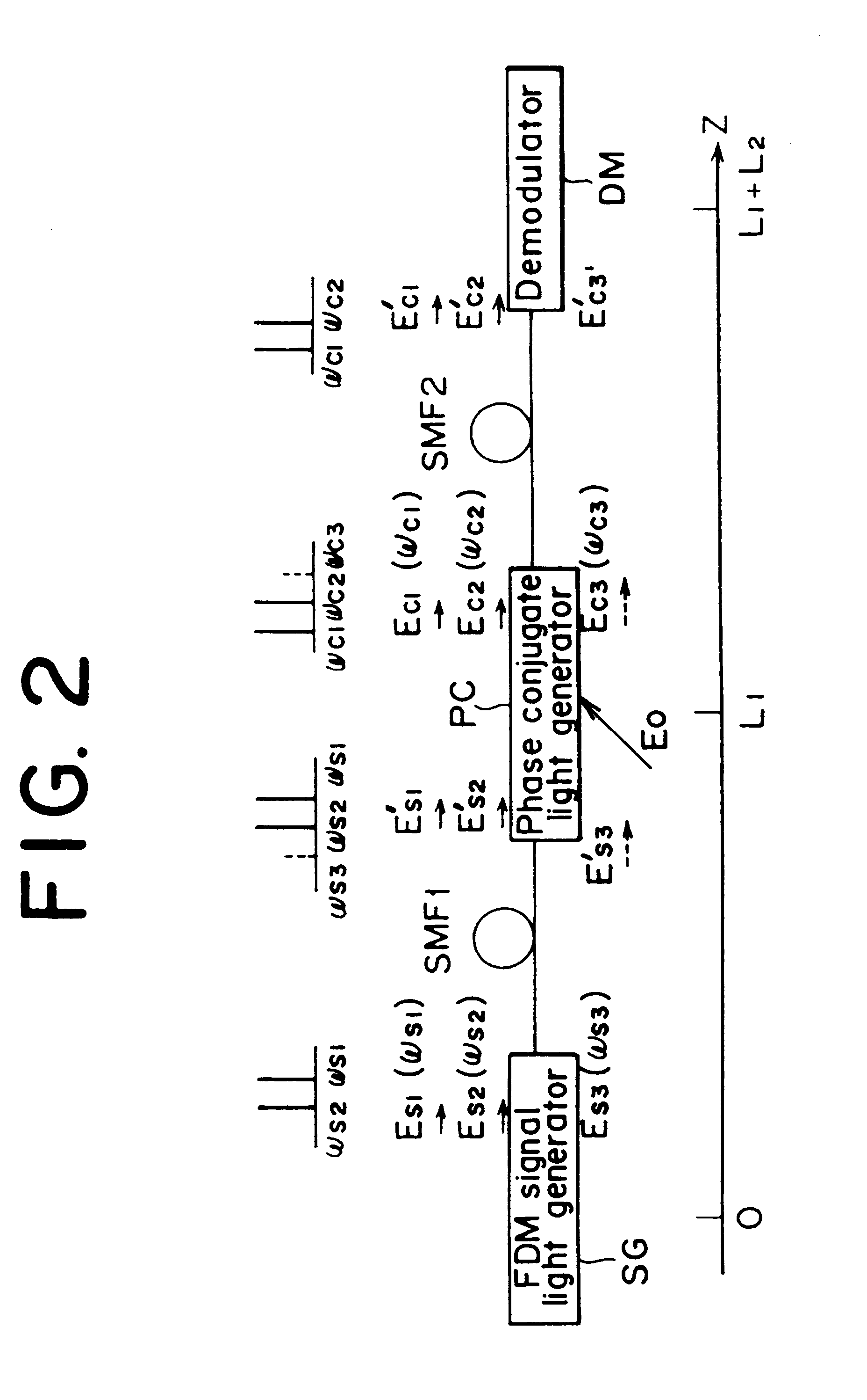
Referring to FIG. 10, there is shown a block diagram illustrating the optical communication system practiced as a fourth preferred embodiment of the invention. This embodiment is characterized by that a phase conjugate light generator PC, a second single-mode fiber SMF-2, and a demodulator DM are contained in receiver 21. For an FDM signal light generator, the transmitter 1 of FIG. 5 is used. Therefore, in the fourth embodiment, a first single-mode fiber SMF-1 provides a transmission path. In this embodiment, the influences of GVD and optical Kerr effect can also be compensated by satisfying the equations (32) and (33). Also, satisfying the equations (34) or (35) can compensate the crosstalk owing to FDM. Although this embodiment requires means for excluding polarization dependency in the receiver 21, it is advantageous in that a pump light of the phase conjugate light generator PC provides a capability in the receiver 21 of selecting wavelengths of FDM signal lights.
Referring to FI...
third embodiment
According to the phase conjugate light generator of FIG. 14, the pump light coming from the laser diode 22 is made confluent with the signal light via the polarization scrambler 41, so that, if the polarization state of the signal light fluctuates over time, the stable operation of the phase conjugate light generator can be ensured by making constant the efficiency of conversion from signal light to phase conjugate light.
The polarization scrambler 41 is ordinarily composed of a 1 / 2 wavelength plate and a 1 / 4 wavelength plate for relatively slow fluctuation of polarization. For example, if the pump light supplied from the laser diode 22 is a generally linearly polarized light, the polarization scrambler operates such that it rotates the plane of polarization of the pump light. Presetting the operating frequency (for example, a reciprocal of a rotational frequency of the polarization plane) of the polarization scrambler 41 to faster than a bit-rate of the transmitting signal permits t...
seventh embodiment
According to the invention, the pump light remaining in generation of the phase conjugate light can be separated from the generated phase conjugate light without using an optical filter (for example, the optical bandpass filter 31 of FIG. 13). The intensity of the pump light used to generate the phase conjugate light is extremely high as compared with the intensities of the signal light and the generated phase conjugate light, so that the embodiment of FIG. 18 is effective in separating the pump light having such a high intensity from the phase conjugate light.
Referring to FIG. 19, there is shown a diagram illustrating the optical communication system practiced as a fifth preferred embodiment of the invention. Halfway on an optical transmission path between a transmitter 1 and a receiver 2, a phase conjugate generator PC is disposed. Between the transmitter 1 and the phase conjugate light generator PC, (N-11) optical amplifiers LA-1, 2, . . . , (N-1) are disposed. Between the phase ...
PUM
 Abstract
Description
Claims
Application Information
 - R&D
- Intellectual Property
- Life Sciences
- Materials
- Tech Scout
- Unparalleled Data Quality
- Higher Quality Content
- 60% Fewer Hallucinations
Browse by: Latest US Patents, China's latest patents, Technical Efficacy Thesaurus, Application Domain, Technology Topic, Popular Technical Reports.
© 2025 PatSnap. All rights reserved.Legal|Privacy policy|Modern Slavery Act Transparency Statement|Sitemap|About US| Contact US: help@patsnap.com


