Engine control monitor for vehicle equipped with engine and transmission

a technology of engine control monitor and transmission, which is applied in the direction of hybrid vehicles, process and machine control, instruments, etc., can solve the problems of additional cost and/or complexity, disadvantages of the above approach, etc., and achieve the effect of reducing system complexity and/or cost, simple structure and simple structur

Inactive Publication Date: 2001-10-16
FORD GLOBAL TECH LLC
View PDF27 Cites 46 Cited by
  • Summary
  • Abstract
  • Description
  • Claims
  • Application Information

AI Technical Summary

Benefits of technology

An advantage of the above aspect of the present invention is a potential for reduced system complexity and/or cost.
By utilizing the end result of vehicle acceleration, a simple structure is achieved that can be applied to various vehicle drive unit configurations. Further, by structuring the vehicle control around desired a

Problems solved by technology

The inventors herein have recognized a disadvantage of the above approach.
In the end,

Method used


Image

  • Engine control monitor for vehicle equipped with engine and transmission
  • Engine control monitor for vehicle equipped with engine and transmission
  • Engine control monitor for vehicle equipped with engine and transmission

Examples


Embodiment Construction

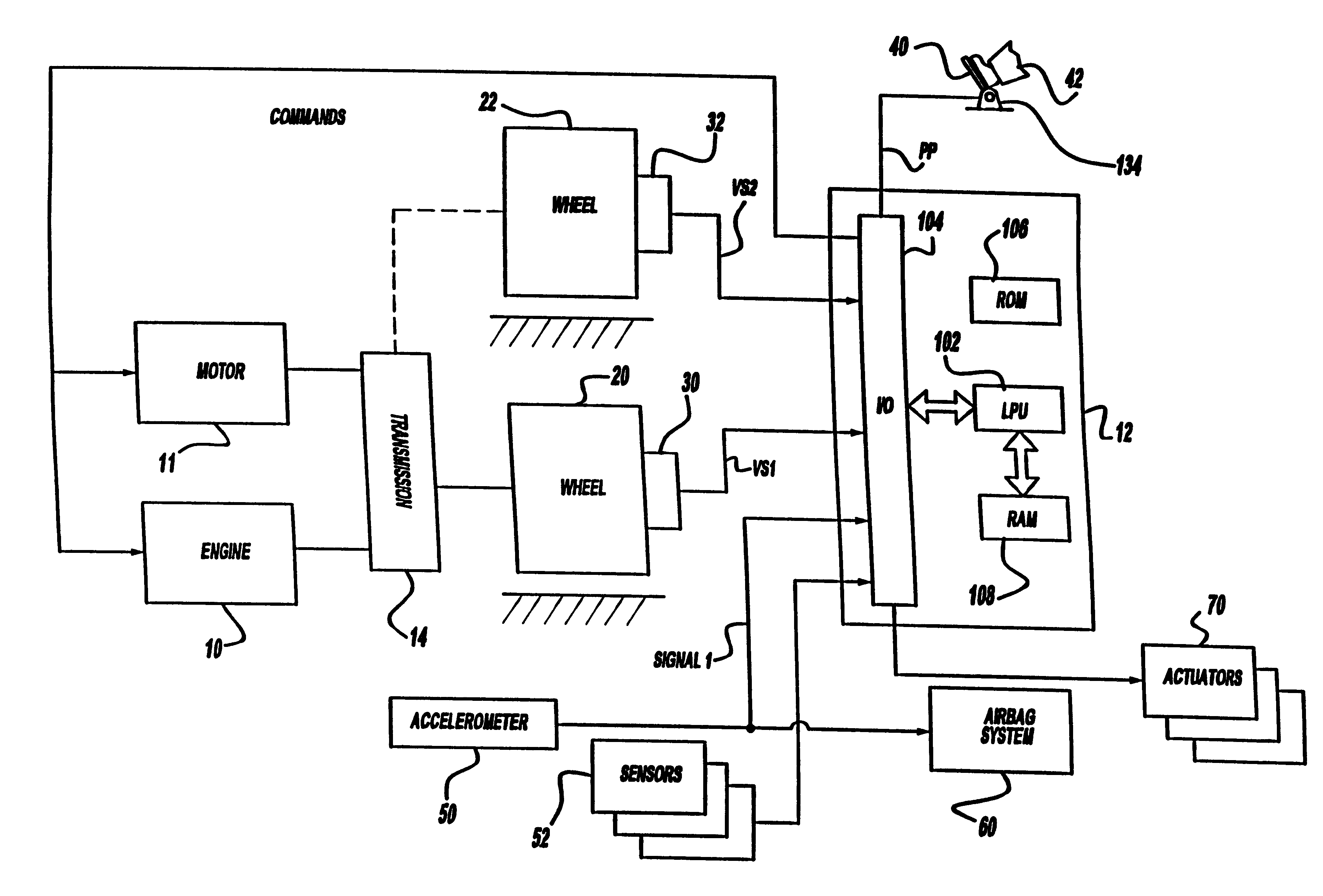
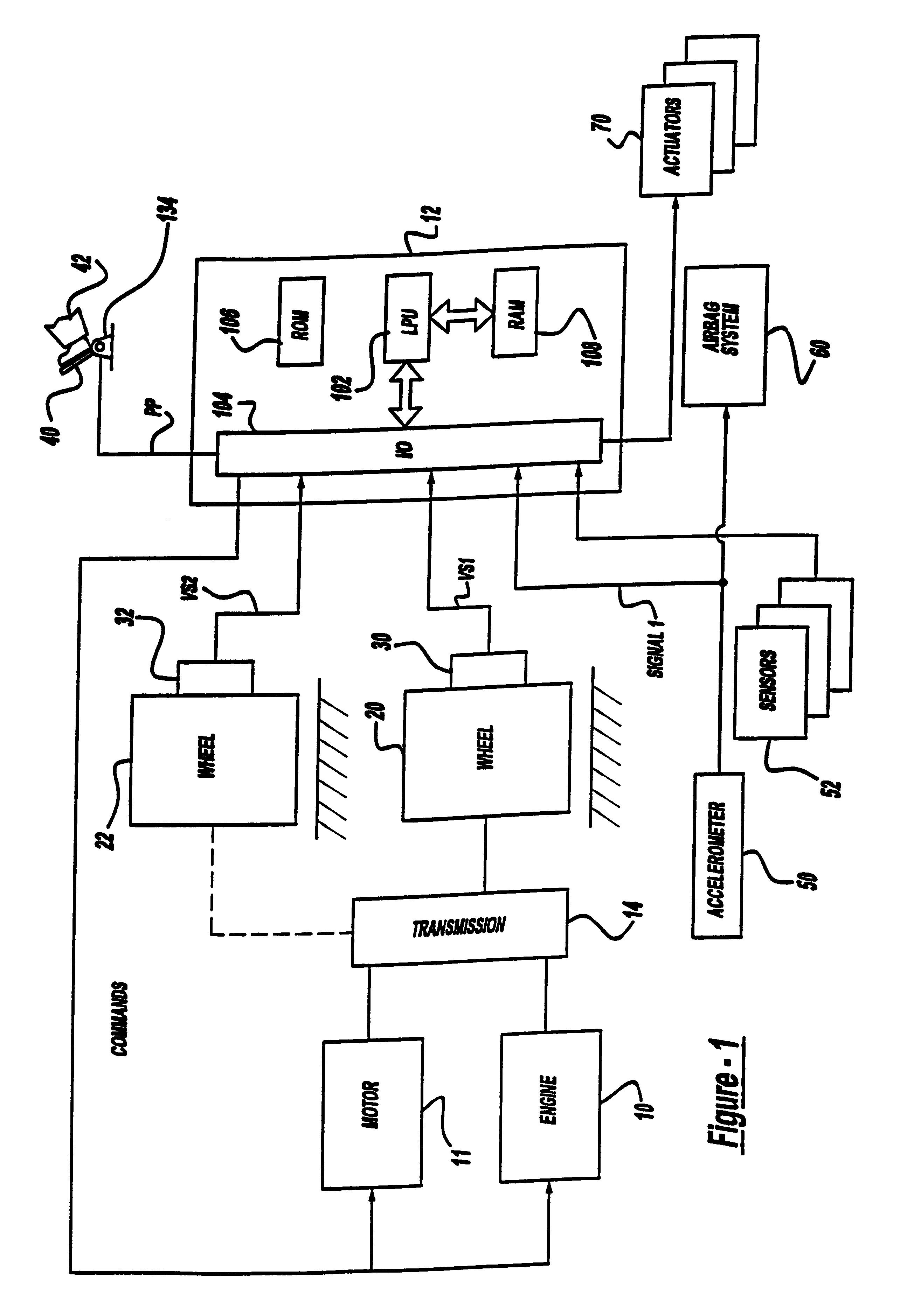
Referring to FIG. 1, internal combustion engine 10 and motor 11 of a vehicle (not shown) are shown coupled to transmission 14. Engine 10 and motor 11 can be coupled in various ways known to those skilled in the art, such, for example, in a parallel fashion, a series fashion, or any combination thereof. Motor 11 can be an electric motor capable of supplying power to or receiving power from transmission 14. For example, motor 11 can be used to provide regenerative braking or to provide the vehicle tractive force from batteries (not shown) that store energy. Transmission 14 is coupled to a first set of drive wheels 20. In addition, to provide all wheel drive, transmission 14 can also be coupled to a second set of drive wheels 22. Transmission 14 can be a combined gear set and torque converter, a continuously variable transmission, or any other power transfer unit known to those skilled in the art and suggested by this disclosure.

Continuing with FIG. 1, accelerator pedal 40 is shown com...


PUM


Abstract

A method for monitoring an electronically controlled drive unit of a vehicle uses actual vehicle acceleration and a preselected vehicle acceleration. Actual acceleration is determined from any of an acceleration sensor or vehicle speed sensors. When actual acceleration is greater than the preselected acceleration, a reaction is initiated to reduce vehicle acceleration.

Description

The field of the invention relates to monitoring of electronically controlled drive units in vehicles.In some engines, an electronically controlled throttle is used for improved performance. In addition, engines also may be controlled using engine output, or torque control where the actual engine torque is controlled to a desired engine torque through an output adjusting device, such as with the electronic throttle, ignition timing, air-fuel ratio, or various other devices.One method to monitor engine control systems determines if actual engine torque is greater than desired engine torque. Actual engine torque is determined in accordance with engine airflow and / or injected fuel amount, and various other factors. Such a method is described U.S. Pat. No. 5,692,472.The inventors herein have recognized a disadvantage of the above approach. In particular, when such a method is utilized with vehicles having multiple torque sources, such as hybrid electric vehicles, several different torqu...

Claims


Application Information

Patent Timeline
IPC IPC(8): B60K6/00B60K31/02B60K6/04B60K31/04B60R21/01B60K6/48B60K6/52B60R21/013B60W10/06B60W10/08B60W10/10B60W20/00
CPCB60K6/48B60K6/52B60K31/047B60W10/06B60W10/08B60W10/10B60W20/00B60R21/013B60W2520/105B60W2720/106Y02T10/6221Y02T10/6265Y02T10/6286Y10S903/945Y10S903/916Y02T10/62B60W2050/0022B60W20/11
Inventor CULLEN, MICHAEL JOHNHIPPLEY, RICHARD JOHN
Owner FORD GLOBAL TECH LLC
Why Eureka
Try Eureka