Symmetric sampling

a signal capture circuit and symmetric sampling technology, applied in the field of symmetric sampling, can solve the problems of impracticality of using two or more signal capture circuits for small precision measuring devices, inability to record and process two or more processing signals at the exact, etc., to achieve accurate measurement position and reduce position errors.

Inactive Publication Date: 2001-10-16
MITUTOYO CORP
View PDF5 Cites 18 Cited by
  • Summary
  • Abstract
  • Description
  • Claims
  • Application Information

AI Technical Summary

Benefits of technology

The invention provides systems and methods for precisely sampling measurement signals to achieve an accurate measurement position at a particular measurement time. This reduces position errors that are proportional to velocity.

Problems solved by technology

However, a single signal capture circuit cannot record and process two or more processing signals at the exact same time in order to generate the extremely precise position measurements.
Moreover, using two or more signal capture circuits is impractical for small precision measuring devices due to space, power, and cost requirements.

Method used


Image

  • Symmetric sampling
  • Symmetric sampling
  • Symmetric sampling

Examples


Embodiment Construction

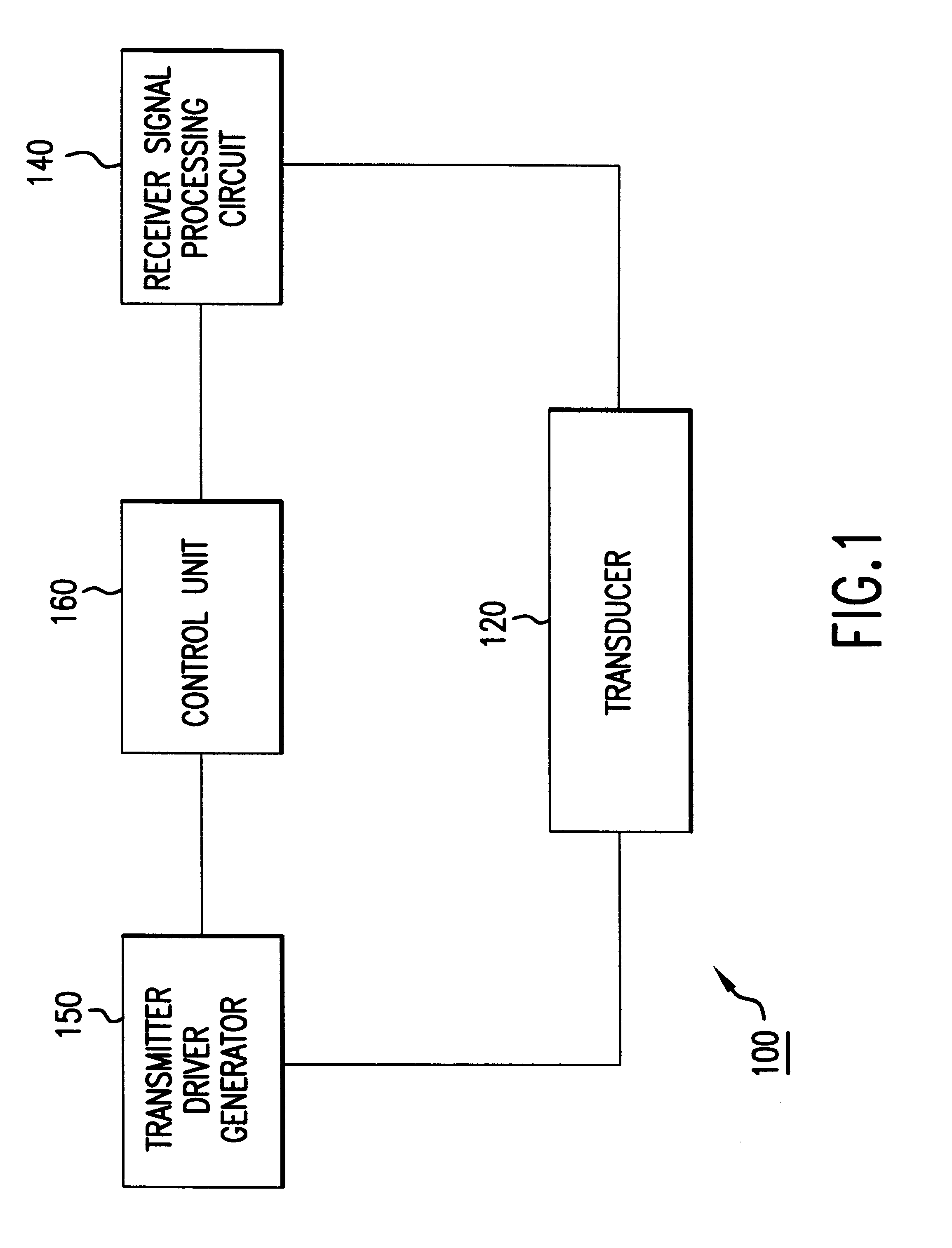
FIG. 1 shows a functional block diagram of an induced current position transducer system 100. The induced current position transducer system 100 includes a transducer 120 connected to a transmitter driver generator 150 and a receiver signal processing circuit 140. The transmitter driver generator 150 and the receiver signal processing circuit 140 are also connected to a control unit 160.

While FIG. 1 shows a functional block diagram for the induced current position transducer system 100, it should be appreciated that the induced current position transducer system 100 is presented as an exemplary embodiment. The symmetric sampling systems and methods of this invention may be implemented on a variety of transducers systems or other appropriate known or later developed precision measuring systems, for example.

Furthermore, it should also be appreciated that the transducer 120 may be implemented using any appropriate known or later developed multiphase transducer, including, for example, ...


PUM


Abstract

The invention provides a method of sampling precision measurement signals to achieve an accurate measurement position at a particular measurement time, such that the measurement accuracy is unaffected by the velocity of motion. The method involves sampling each signal during a predetermined sampling period such that a signal from one sensor is sampled first, a signal from a second sensor sampled second, etc., and then the signals are sampled in reverse order such that the first signal sampled is sampled last. These sampled signals are averaged and produce a precision measurement at a time measured at one-half of the sampling time. In addition, this method can be applied to the use of separate scale tracks where each scale track is alternately sampled, or alternatively, where one scale track is sampled in the middle of the sampling period of another scale track.

Description

BACKGROUND OF THE INVENTION1. Field of InventionThis invention relates to sampling electronic signals. More particularly, this invention is directed to sampling electronic positioning signals generated by induced current linear and rotary position transducers.2. Description of Related ArtVarious movement or position transducing systems are currently available. U.S. patent application Ser. No. 08 / 788,469, filed Jan. 29, 1997, and incorporated herein by reference in its entirety, discloses an absolute position transducer for high accuracy applications, such as linear or rotary encoders, electronic calipers and the like. The absolute position transducer uses two members movable relative to each other. The first member contains at least one active transmitter for generating a magnetic field and at least one receiver for receiving the generated magnetic field. The passive second member includes passive flux modulating elements that modulate the received field depending on their position ...

Claims


Application Information

Patent Timeline
Patent Type & Authority Patents(United States)
IPC IPC(8): G01D5/12G01D5/20H03M1/06H03M1/22G01B7/00G01D5/244G01D5/245
CPCG01D5/2053H03M1/0658H03M1/22
Inventor ANDERMO, NILS INGVARSKURNIK, DAVIDDELANY, MARK L.
Owner MITUTOYO CORP
Why Eureka
Try Eureka