

Shoe ventilation
- Summary
- Abstract
- Description
- Claims
- Application Information
AI Technical Summary
Benefits of technology
Problems solved by technology
Method used
Image

Examples
Embodiment Construction
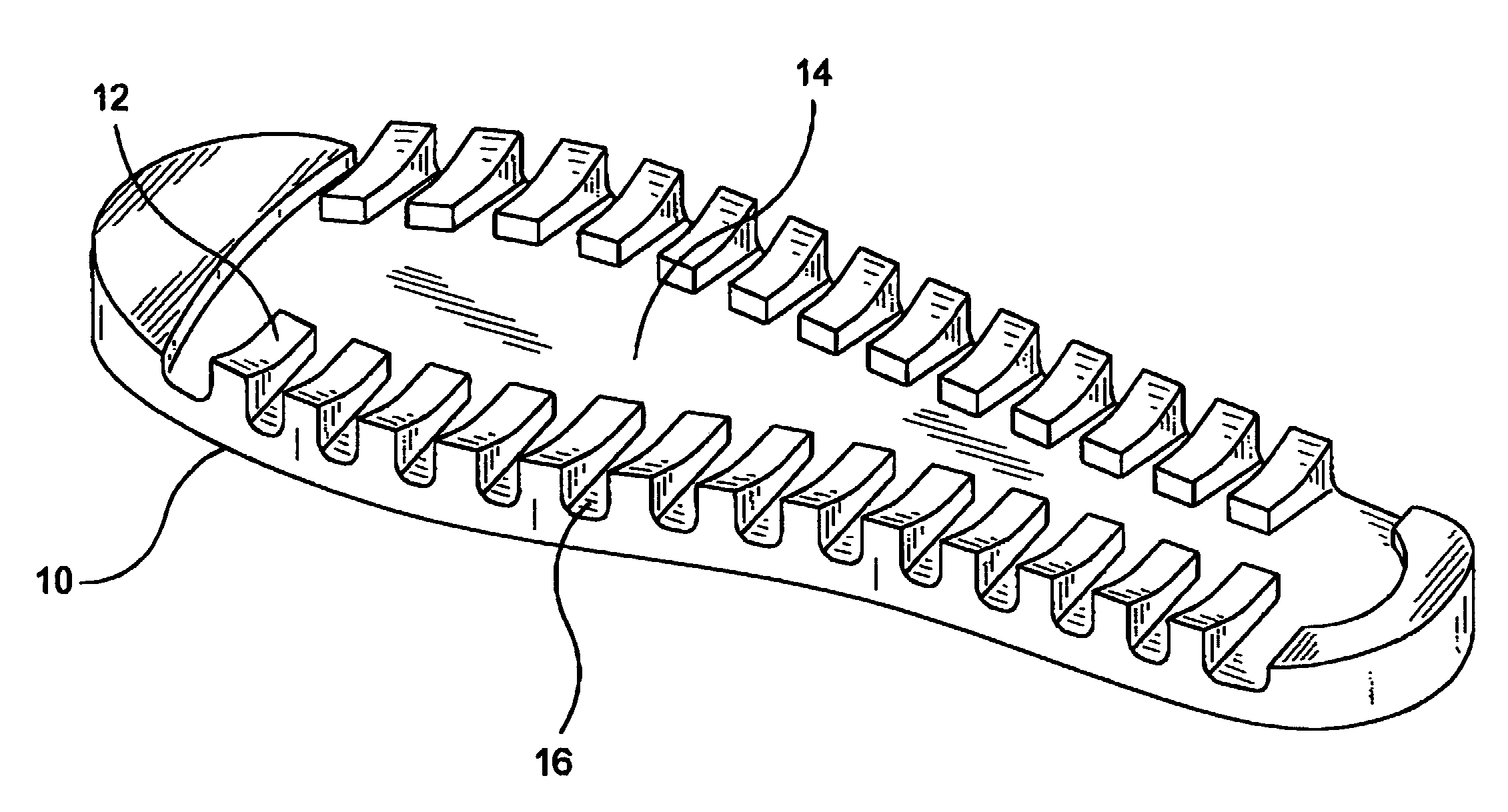
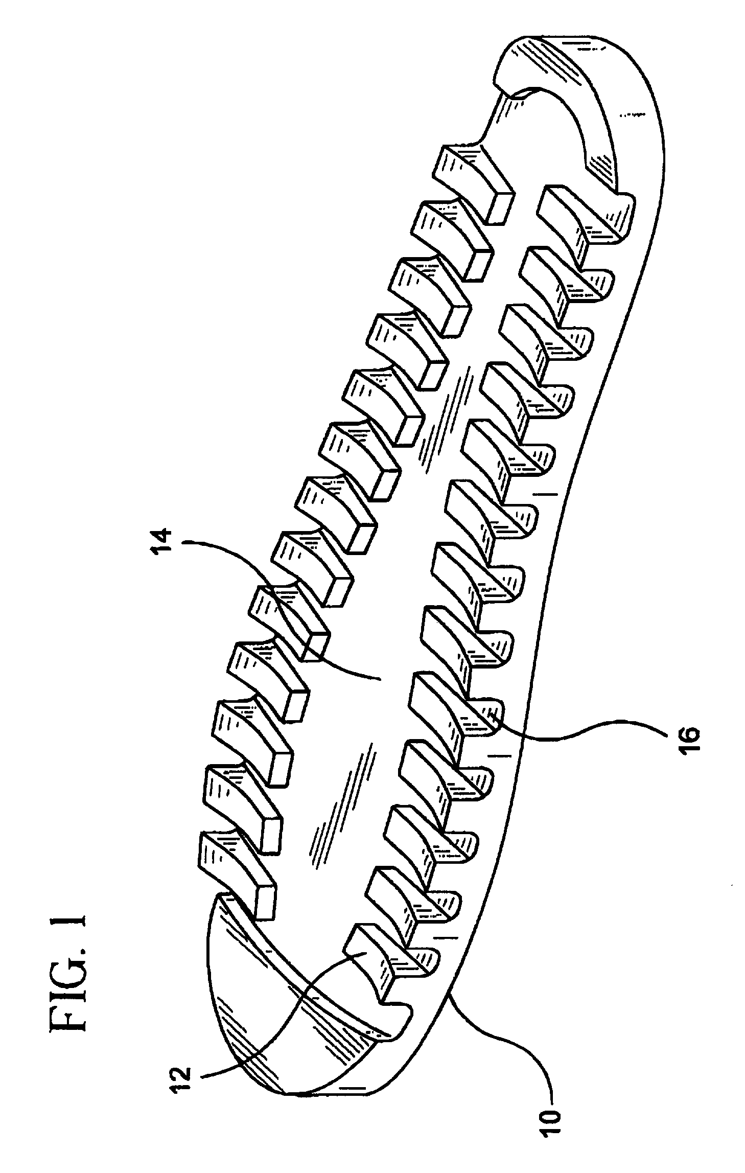
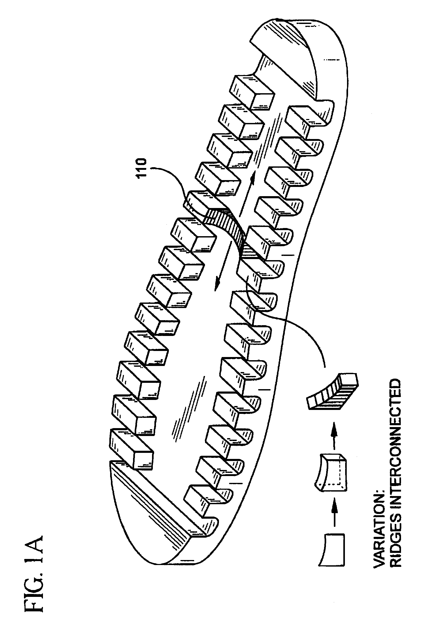
This invention provides a unique approach to the ventilation of a shoe interior and the subsequent exhaust of foot heat and moisture. The invention principle utilizes an efficient air cavity allowing foot heat and moisture to escape the immediate foot area and exhaust into free open space. This is achieved through a unique sole design, employing a dual-layer sole system. The layers of this dual-layer sole are integrated in a manner which allows an air cavity area to exist between them. This air cavity area acts as an interfacing medium between the inner foot area and free open space outside the immediate shoe area.
Foot-air and moisture flow is achieved by employing a series of perforations and / or cutouts throughout the inner primary-layer sole. These perforations extend through the surface of this inner sole immediately into an air cavity area. In turn, this air cavity area extends ultimately into free open space outside the shoe via multiple ventilation ports. This system provides ...
PUM
 Abstract
Description
Claims
Application Information