Mineral fiber insulation having thermoplastic polymer binder and method of making the same

a technology of thermoplastic polymer and mineral fiber insulation, which is applied in the field of mineral fiber insulation products and methods of making the same, can solve the problems of increasing the cost of manufacturing process, increasing the cost of production, and the binder material on the mineral fibers is sticky, so as to reduce the amount of binder that is needed, avoid or substantially reduce contamination and other problems, and improve the effect of quality

Inactive Publication Date: 2008-08-21
CERTAINTEED CORP
View PDF17 Cites 6 Cited by
  • Summary
  • Abstract
  • Description
  • Claims
  • Application Information

AI Technical Summary

Benefits of technology

[0012]The manufacturing system and method avoids or substantially reduces contamination and other problems associated with phenolic resins by using a non-aqueous, formaldehyde-free thermoplastic polymer binder to bind the insulation fibers. Use of a non-aqueous solution lessens the storage area needed for the binder and generally provides a simpler, cleaner, more efficient process. Further, the final insulation product is formaldehyde-free, or substantially free.

Problems solved by technology

One of the problems with applying aqueous organic binders to cylindrical veils of mineral fibers is that a portion of the binder tends to evaporate prior to contact between the liquid binder drop and a mineral fiber in the veil.
This evaporated binder material becomes a contaminant in the exhaust air stream of the process and must be cleaned, adding significant expense to the manufacturing process.
Further, the binder material on the mineral fibers tends to be sticky and necessitates extensive cleaning of the fiber collection apparatus in order to avoid the formation of product defects.
Another problem associated with the application of the thermosetting phenolic binder material is that a curing process is required.
Typical problems associated with curing include operational costs associated with the curing oven, the cost of handling pollution issues, degree of cure problems and product integrity problems.
However, because these acrylic binders are applied in aqueous form, they are difficult to use since a low PH is required for storage and application, at least when compared with binders in dry form.
It is very difficult to obtain uniformly blended mats of glass and organic fibers using this system.
As with the system of the '584 patent, it is very difficult to obtain uniformly blended mats of glass and organic fibers using this system.

Method used


Image

  • Mineral fiber insulation having thermoplastic polymer binder and method of making the same
  • Mineral fiber insulation having thermoplastic polymer binder and method of making the same
  • Mineral fiber insulation having thermoplastic polymer binder and method of making the same

Examples


first embodiment

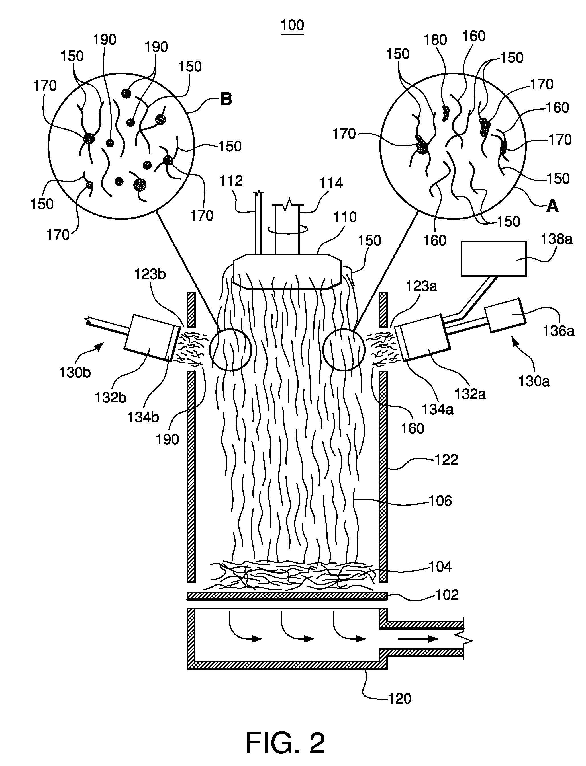
[0027]FIG. 2 is a schematic front elevational view of the insulation manufacturing system 100. The system 100 includes thermoplastic binder applicator devices 130a and / or 130b disposed to introduce thermoplastic binder directly into the veil 106. More specifically, the applicator devices 130a, 130b introduce a non-aqueous, formaldehyde-free thermoplastic binder to the veil 106. In one embodiment, the applicator 130a is a hot melt applicator which blows thermoplastic binder fibers 160 into veil 106 to commingle with rotary fibers 150 from fiberizing apparatus 110. Applicator 130a includes a hot melt gun 132a with a die head or nozzle labeled 134a connected thereto. A source of hydraulic and / or pneumatic pressure 136a is coupled to the gun 132a for use in extruding the thermoplastic and / or blowing the extruded thermoplastic. A thermoplastic polymer melter or extruder 138a is also coupled to the gun 132a. Melted thermoplastic binder is provided to the gun 132a from polymer melter 138a ...

second embodiment

[0038]FIG. 3 is a schematic front elevational view of an insulation manufacturing system 100A according to the system. The system is identical to that shown in FIG. 2 and described above except for replacement of some or all of melt blown applicators 130a and / or 130b with polymer powder provider apparatus 210. Polymer powder provider apparatus 210 provides the thermoplastic binder in solid, powdered form, shown as particles 200, which are blown into veil 106. Some of the particles may melt upon contact with veil 106, forming melt bonds 170 with the rotary fibers 106.

[0039]In one embodiment, the apparatus 210 includes a chamber 212 for storage of the thermoplastic binder in powdered form. The binder particles 200 can be blown from the chamber 212 using air source (e.g., a blower) 216 through pipe or other conduit 214 into the forming hood 122 to veil 106. In one embodiment, the powdered binder particles are ground from a source material using grinding techniques familiar to those in ...


PUM

PropertyMeasurementUnit
lengthaaaaaaaaaa
diametersaaaaaaaaaa
diametersaaaaaaaaaa

Abstract

A method of forming a fibrous insulation product includes forming at least one fibrous veil including first fibers and blowing a non-aqueous, formaldehyde-free, thermoplastic binder in powder, liquid or fibrous form into said veil during said forming step to form a mixture of the binder and the first fibers. When in fibrous form, the binder fibers have average length of less than or equal to about 15 mm. The mixture is collected on the forming belt and formed into an insulation batt, board or molding media.

Description

FIELD OF THE INVENTION[0001]The present invention relates generally to mineral fiber insulation products and methods of making the same.BACKGROUND OF THE INVENTION[0002]Batt insulation is commonly manufactured by fiberizing mineral fibers from a molten mineral bath (e.g., molten glass) by forcing them through a spinner rotating at a high number of revolutions per minute. The fine fibers are then contacted by a pressurized hot gas to draw the fibers to a useable diameter and length. The fibers are typically sprayed with an organic material, such as a phenol / formaldehyde binder. The fibers are then collected and distributed on a conveyor to form a mat. The resin is then cured in a curing oven. The mat is then sliced into lengthwise strips having desired widths and chopped into individual batts. In some cases, a facing material, such as Kraft paper coated with a bituminous material or other vapor retarder, is added to the mat prior to the cutting step.[0003]Often, the organic material ...

Claims


Application Information

Patent Timeline
Patent Type & Authority Applications(United States)
IPC IPC(8): E04B1/74
CPCD04H1/60D04H1/641E04B2001/7687D04H13/008D04H1/642D04H1/4218D04H1/587D04H1/64D04H1/732
Inventor YANG, ALAINTOAS, MURRAY S.
Owner CERTAINTEED CORP
Why Eureka
Try Eureka