Radar systems

Inactive Publication Date: 2001-10-23
BAE SYSTEMS PLC
View PDF6 Cites 24 Cited by
  • Summary
  • Abstract
  • Description
  • Claims
  • Application Information

AI Technical Summary

Problems solved by technology

However, besides the reflections from the wanted targets, e.g. aircraft, other reflections from unwanted objects occur.
However, this does not completely solve the problem because some targets may have zero radial speed even if they are moving rapidly in a direction tangential to the radar.
For this reason, clutter maps have to date only been successfully app

Method used


Image

  • Radar systems
  • Radar systems
  • Radar systems

Examples


Example

The four improvements in accordance with the present invention will now be described in detail.

Compensation of radar movement

Compensation is made for the movement of the radar platform by storing the platform starting position, and taking this as the origin of co-ordinates. At later times the new platform position is computed as an offset from the starting position and stored. Whenever a reflected signal is received, this offset is added to the position of the scatterer, and the resulting corrected position is used to define its location in the clutter map.

Storing the offset is done as follows. Suppose the ship's motion is known and defined by (x.sub.0 (t),y.sub.0 (t)) at time t. Platform motion is then taken into account by using (x+x.sub.0 (t),y+y.sub.0 (t)) as the position of the clutter map.

The clutter map cell number can then be computed, and the method for doing this is dependent on the co-ordinate system in use for the map. The present invention is not dependent on the co-ord...


PUM


Abstract

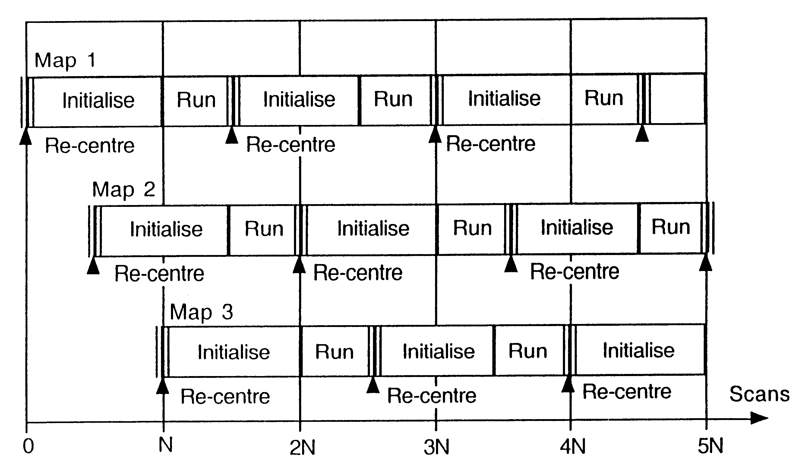
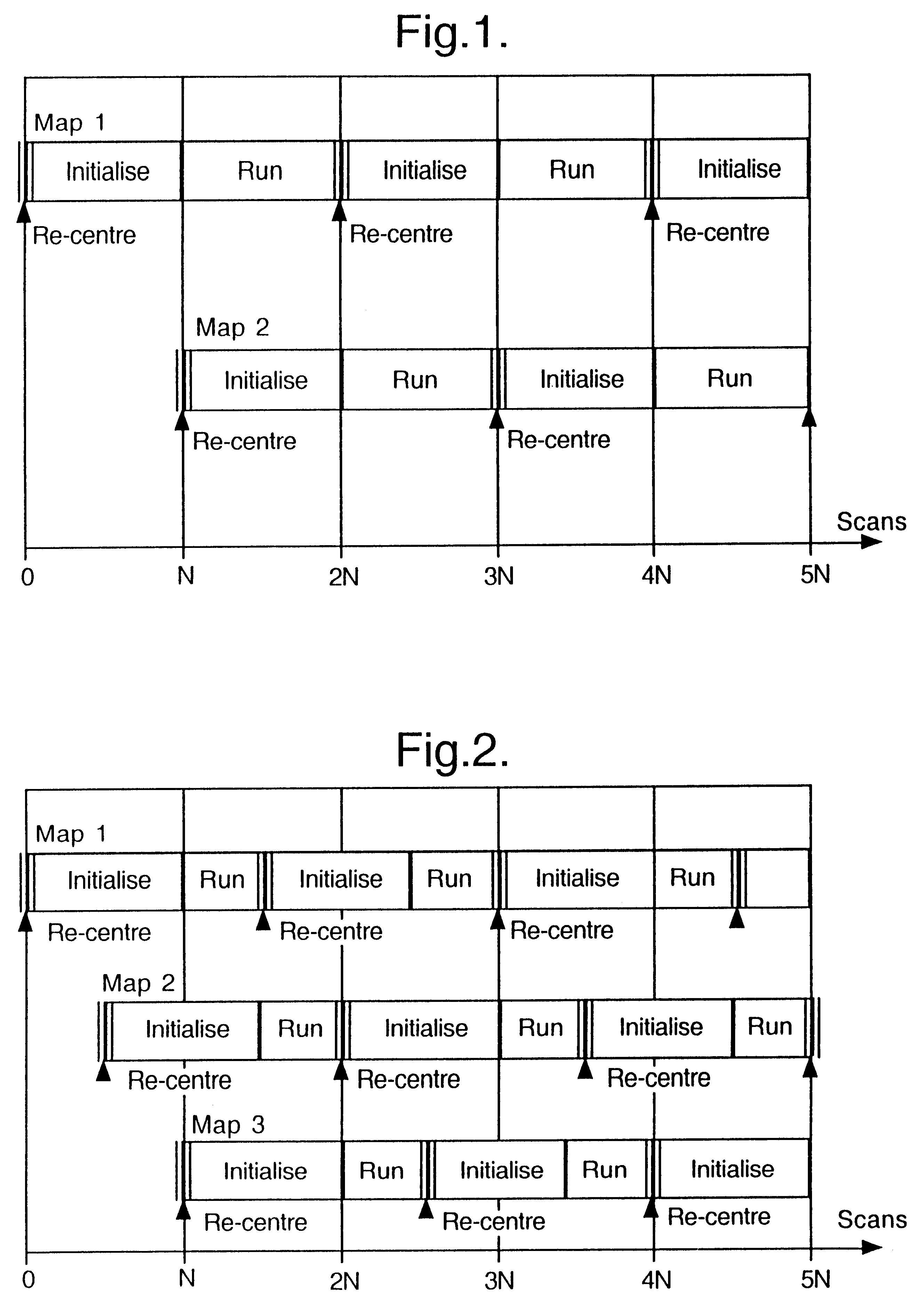
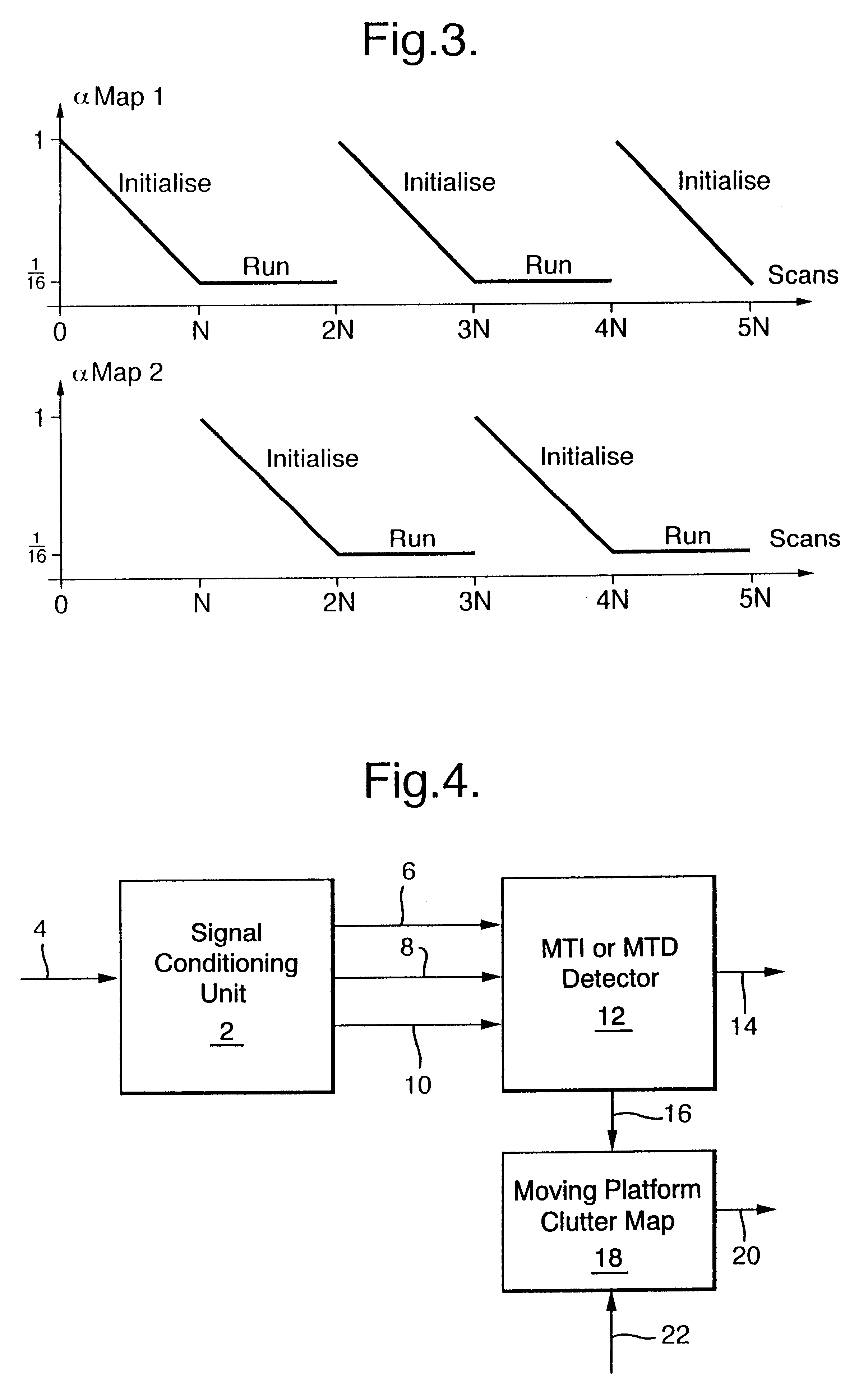
In a radar system it is necessary to distinguish signals reflected from wanted targets such as aircraft from those reflected from fixed terrain features, known as clutter. The clutter signals can in some cases be significantly stronger than the wanted signals. One method for dealing with land clutter is the use of a high resolution clutter map. The area around the radar is considered to be divided into cells, and an array of background signal estimates is maintained for these cells. Whenever a signal is received by the radar, it is compared with the stored background level for the cell it occupies, and a detection is only reported if the signal exceeds the background by a pre-set threshold. Received signals are also used to modify the stored background levels so that the clutter map adapts to the reflections from clutter which are present over long periods. Clutter maps have so far only been used successfully for radars at fixed locations. In the case of a ship-borne radar near land, a conventional clutter map will not work well. This is because as the ship moves, the positions of land scatterers relative to the ship will not be fixed. Individual terrain features will therefore be moved from one clutter map cell to another. In the cell into which a strong scatterer moves, the land clutter reflections will be reported as targets until the stored background has had time to adapt to the new higher level. Similarly, in the cell which the scatterer has left, the stored background level will be higher than necessary, and may cause actual targets to be suppressed until it has had time to adapt to the new lower clutter level.

Description

1. Field of the InventionThe present invention relates to radar systems and in particular to the suppression of unwanted signals received by a radar system which have been reflected from fixed objects (clutter) such as terrain features and buildings, in the case when the radar is mounted on a moving platform such as a ship.2. Discussion of Prior ArtA radar system operates by transmitting electromagnetic signals and receiving these same signals after they have been reflected from targets. However, besides the reflections from the wanted targets, e.g. aircraft, other reflections from unwanted objects occur. These unwanted objects are referred to as clutter, and may include terrain features such as hillsides and cliffs, man made objects such as buildings and fences, and weather phenomena such as rain. The unwanted reflections may in some cases be greater than the reflections from targets.Methods for suppressing the unwanted reflections and retaining only signals from targets generally ...

Claims


Application Information

Patent Timeline
IPC IPC(8): G01S13/00G01S13/524G01S13/538G01S7/32
CPCG01S13/5242G01S13/5244G01S13/5248
Inventor WILLS, ROBERT WBAKER, JONATHAN H
Owner BAE SYSTEMS PLC
Why Eureka
Try Eureka