Multi-mode fluid injection system

a fluid injection system and multi-mode technology, applied in the direction of cleaning processes and equipment, cleaning liquids, chemistry apparatus and processes, etc., can solve the problems of high performance demands on these tools, affecting the productivity of high-cost professionals, and large and/or heavy equipmen

Inactive Publication Date: 2001-10-30
MARKET GAP ANALYSIS GRP
View PDF21 Cites 27 Cited by
  • Summary
  • Abstract
  • Description
  • Claims
  • Application Information

AI Technical Summary

Problems solved by technology

Performance demands on these tools are high as they directly affect the productivity of high cost professionals.
Many such apparatus are large and/or heavy, difficult to carry and of limited use in servicing pipes and tubing located in remote or difficult to reach places.
Air compressors and gas cartridges reflect an additional expense to the plumbing and air conditioning service industry.
Moreover,

Method used


Image

  • Multi-mode fluid injection system
  • Multi-mode fluid injection system
  • Multi-mode fluid injection system

Examples


Embodiment Construction

of the Operation of the Multi-Mode Fluid Injection System

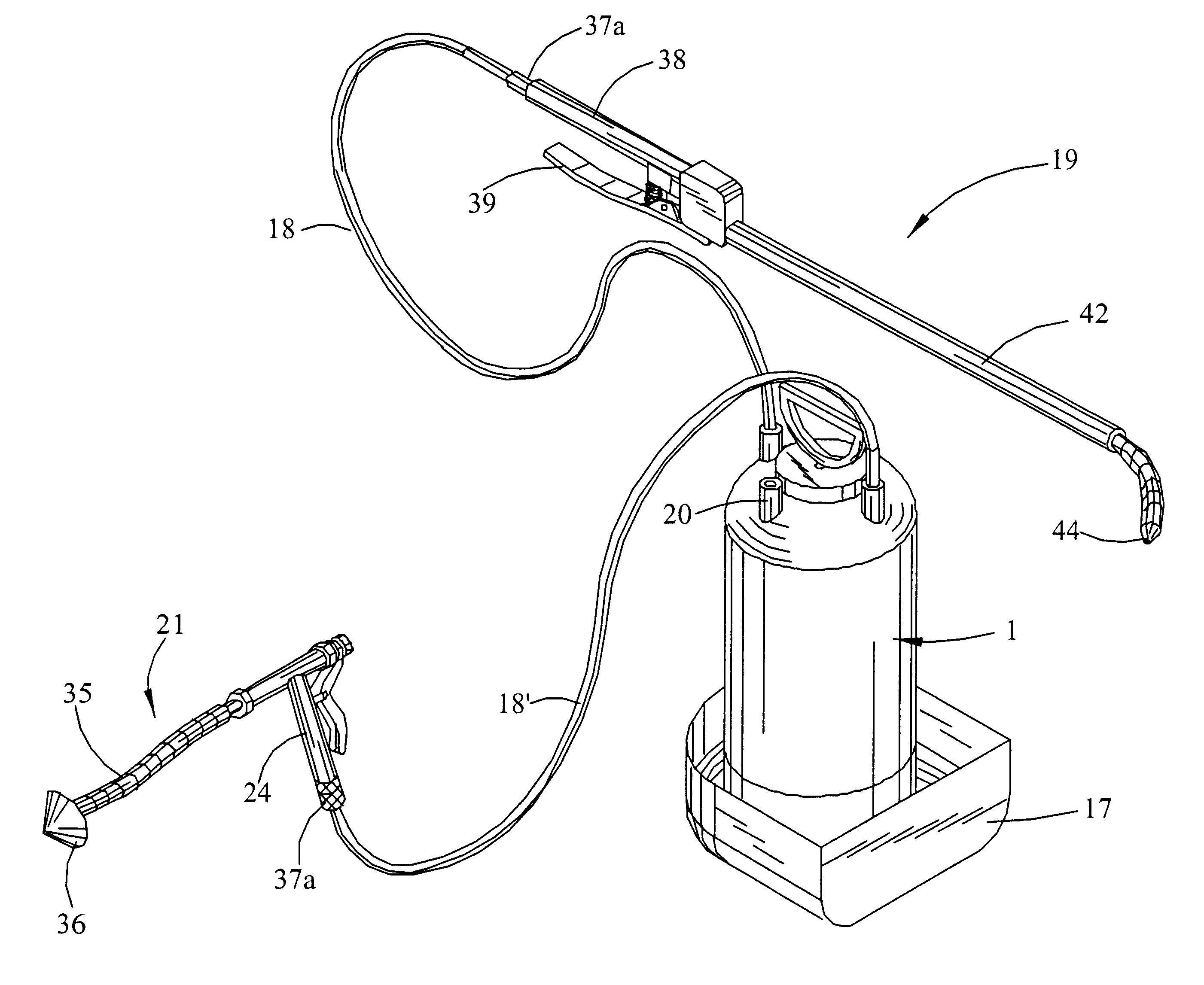
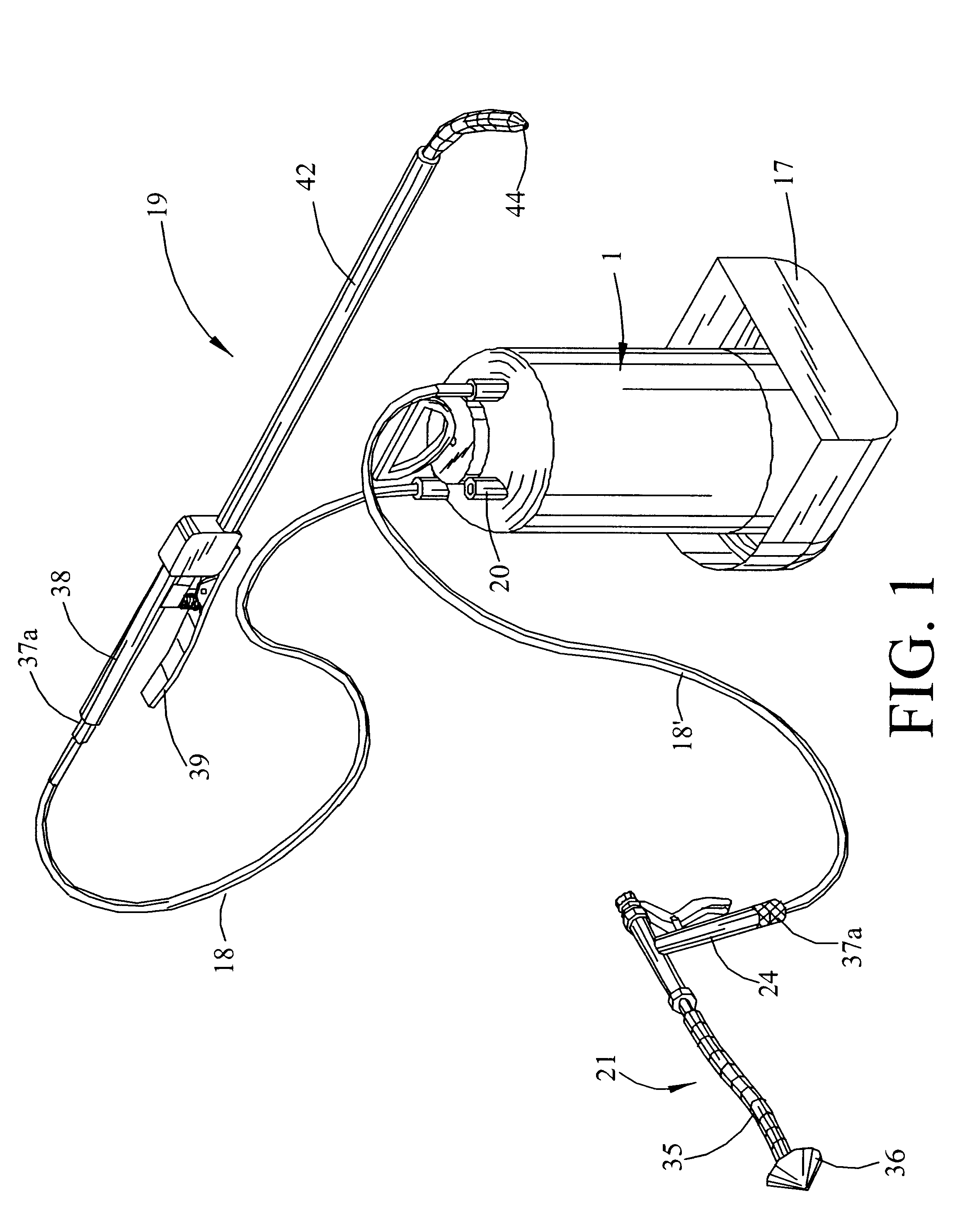
The method of operation and use of the multi-mode fluid injection system of the present invention is described below with reference to FIGS. 1 and 5.

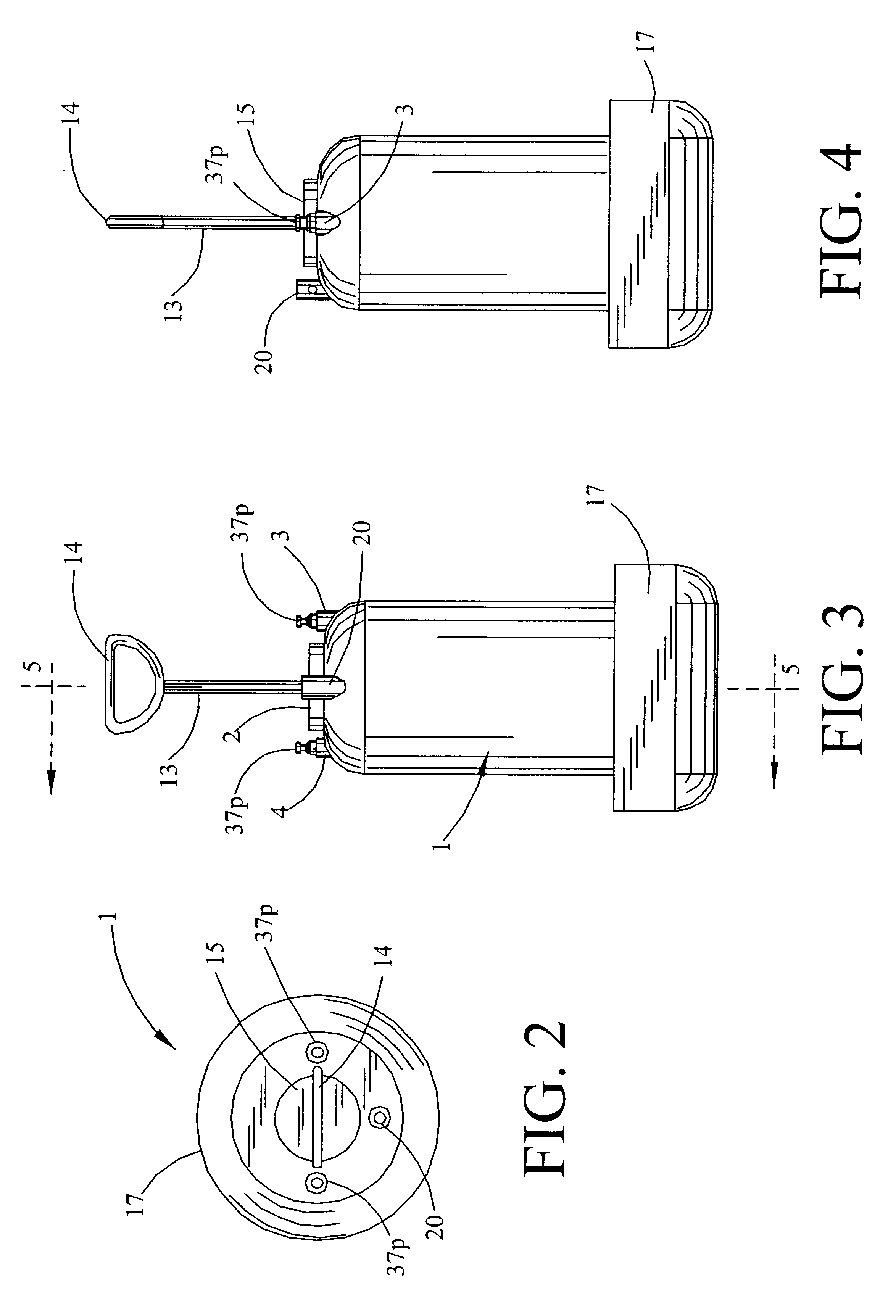
Screw cap 15 is removed together with the hand pump from tank 1 and a liquid, typically water or a cleaning solution of some sort, is introduced into tank aperture 2 to only partially fill the chamber of tank 1. Cap 15 is replaced and screwed tight, securing the hand pump within tank 1. Handle 14 is then pumped to pressurize tank 1 and its contents. An optional pressure gauge, not shown, can be used to determine when sufficient internal pressure has been attained.

Next an applicator, as for example either injection gun applicator 21 or wand sprayer applicator 19, is coupled to either air port 3 or liquid port 4 via hoses 18 or 18' and quick release fittings 37a and 37p. If port 3 is selected, the pressure in tank propels air through port 3 and hose 18 to the selected applicator. If...


PUM


Abstract

A compact, highly portable, multi-mode fluid injection system able to reach difficult to access places to efficiently service a variety of diameter pipes, tubing and related components. The system comprises a tank having a first port which allows access to the tank's upper contents and a second port which allows access to the tank's lower contents, a means for introducing liquid into the tank, a hand pump built into the tank to pressurize the tank and its contents, one or more applicators, and flexible hoses which connect the applicators to the first and/or second port to supply the applicators with the tank's contents. The system is capable of producing, alternatively, pressurized liquid or gas without an independently powered air compressor or consumable gas cartridges, and without having to empty and/or fill the tank. An onboard means for stowing the hose conduits, an injection gun applicator having a small travel-high flow valve with adjustable accumulation chamber, and applicators having stiff-flexible tips and tip extensions are also described.

Description

BACKGROUND OF INVENTIONRELATED PATENT APPLICATIONSThere are no related patent applications.The present invention relates generally to pressurized injection systems used to unclog, clean and service pipes, tubing and related equipment. More particularly, this invention, describes a compact, highly portable, high pressure fluid injection system able to reach difficult to access places to efficiently service a variety of diameter pipes and tubing.DESCRIPTION OF THE PRIOR ARTField work in the air conditioning and plumbing business requires a variety of rugged but light weight tools. Performance demands on these tools are high as they directly affect the productivity of high cost professionals.There exists a wide variety of commercially available apparatus regularly used to unclog, clean and otherwise maintain plumbing and appliances comprised of pipes and tubing. Many such apparatus are large and / or heavy, difficult to carry and of limited use in servicing pipes and tubing located in re...

Claims


Application Information

Patent Timeline
IPC IPC(8): B05B9/08B08B3/02B08B9/04B08B9/02B05B15/00B05B15/06B05B9/01B05B9/00
CPCB05B9/0816B08B3/026B08B9/0495B05B9/01B05B15/066B05B15/652
Inventor CROFFORD, JOE
Owner MARKET GAP ANALYSIS GRP
Why Eureka
Try Eureka