Cam micro-finishing tool

a micro-finishing and tooling technology, applied in the field of micro-finishing tooling, can solve the problems of time-consuming and expensive replacement, affecting the precision of the tool, and requiring the replacement of worn components, so as to avoid wear, replace the insert inexpensively, and replace the effect of easy replacemen

Inactive Publication Date: 2001-10-30
FORD GLOBAL TECH LLC
View PDF13 Cites 13 Cited by
  • Summary
  • Abstract
  • Description
  • Claims
  • Application Information

AI Technical Summary

Benefits of technology

By eliminating the rotatable connections, a machine according to the present invention avoids wear at the rotatable pinned connections. Furthermore, the replaceable insert is inexpensive and is easily replaced.

Problems solved by technology

These pins and articulating connections are areas which have been discovered to present wear problems with this device.
As these connections wear, the precision of the tool is compromised and therefore these worn components must be replaced.
Such replacement is both time consuming and expensive, as these wear items are unique to these machines and must be manufactured specifically for this use.
As discussed above, these pivots wear and therefore require replacement of the pins and of the tool hanger 116.
This is, again, time consuming and expensive because these are custom parts for this particular machine.
Due to the permanent attachment and unique shape of these shoes, it is expensive and time consuming to service them upon wear, as in the other devices described above. FIGS. 2-4 illustrate a two-piece shoe design utilizing shoe portions 118 permanently attached to jaw arms 121 and 122.
Similar to that described above, these shoe portions 118 have a unique shape and are expensive to produce and time consuming to replace.
As shown in these figures, the universal shoe is complex, requiring several pieces and unique designs, thereby increasing the expense of these parts and the difficulty to service these upon wear.
This, again, will produce wear at the pin connections, thereby requiring service of additional parts.

Method used


Image

  • Cam micro-finishing tool
  • Cam micro-finishing tool
  • Cam micro-finishing tool

Examples


Embodiment Construction

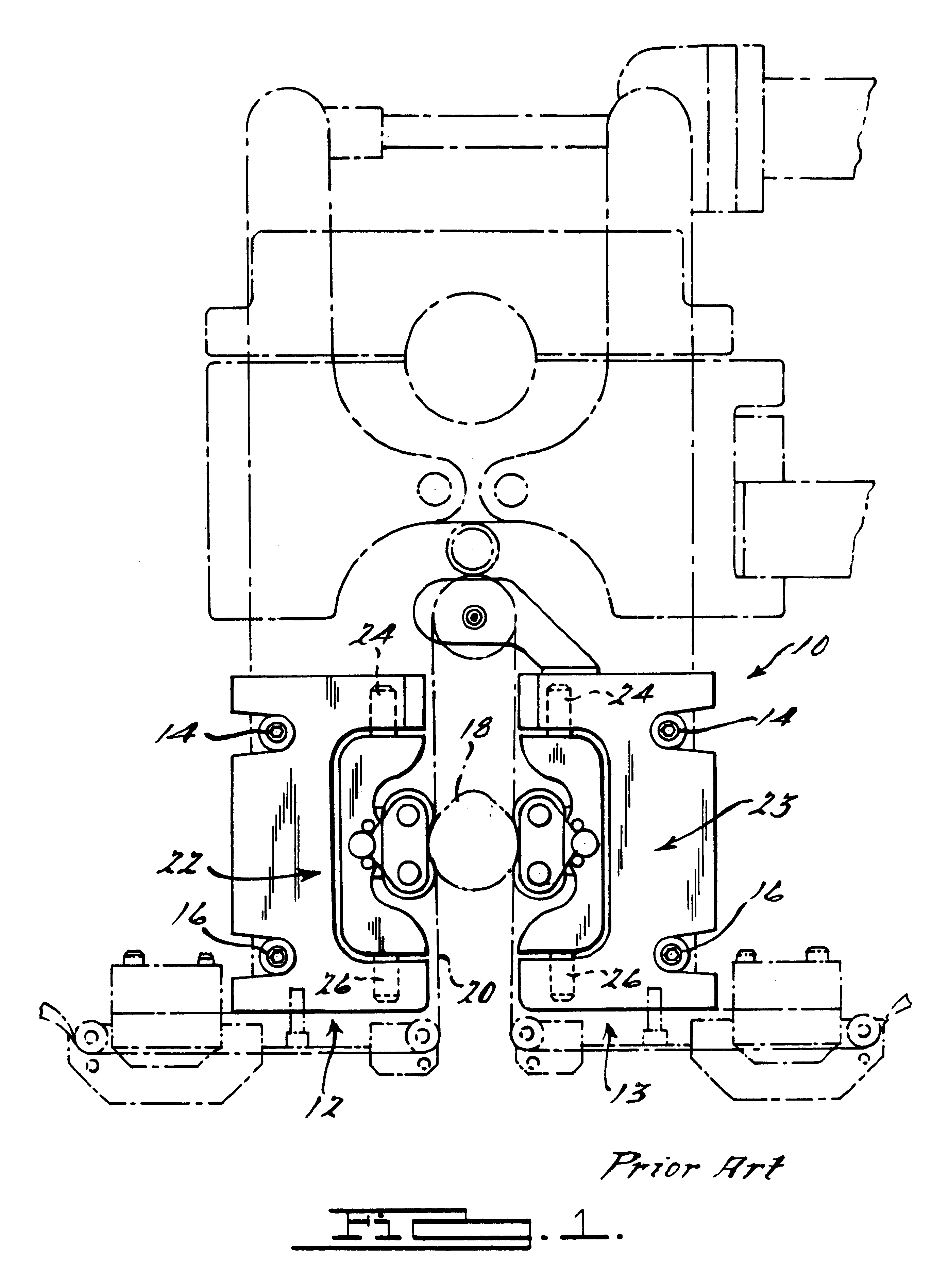
As shown in prior art FIG. 1, a partial view of a micro-finishing machine 10 is shown. The machine 10 includes a pair of shoes 12, 13 attached thereto. The shoes 12, 13 are secured using fasteners 14 and 16. A workpiece 18 is finished between the shoes 12 and 13. The shoes 12 and 13 provide reinforcement for a tape 20 which micro-finishes the surface of the workpiece 18, such as a crankshaft for an internal combustion engine. The shoes 12, 13, as described with reference to first shoe 12, include a pair of support members 22, 23 against which the tape 20 bears. The members 22, 23 have a pinned connection at 24, 26 to the shoes 12, 13. The members 22, 23 thus rotate with respect to the shoes 12, 13 about the pins 24 and 26. As described above with reference to the prior art in the Background section, the shoes 12, 13 wear at these pinned connections 24, 26.

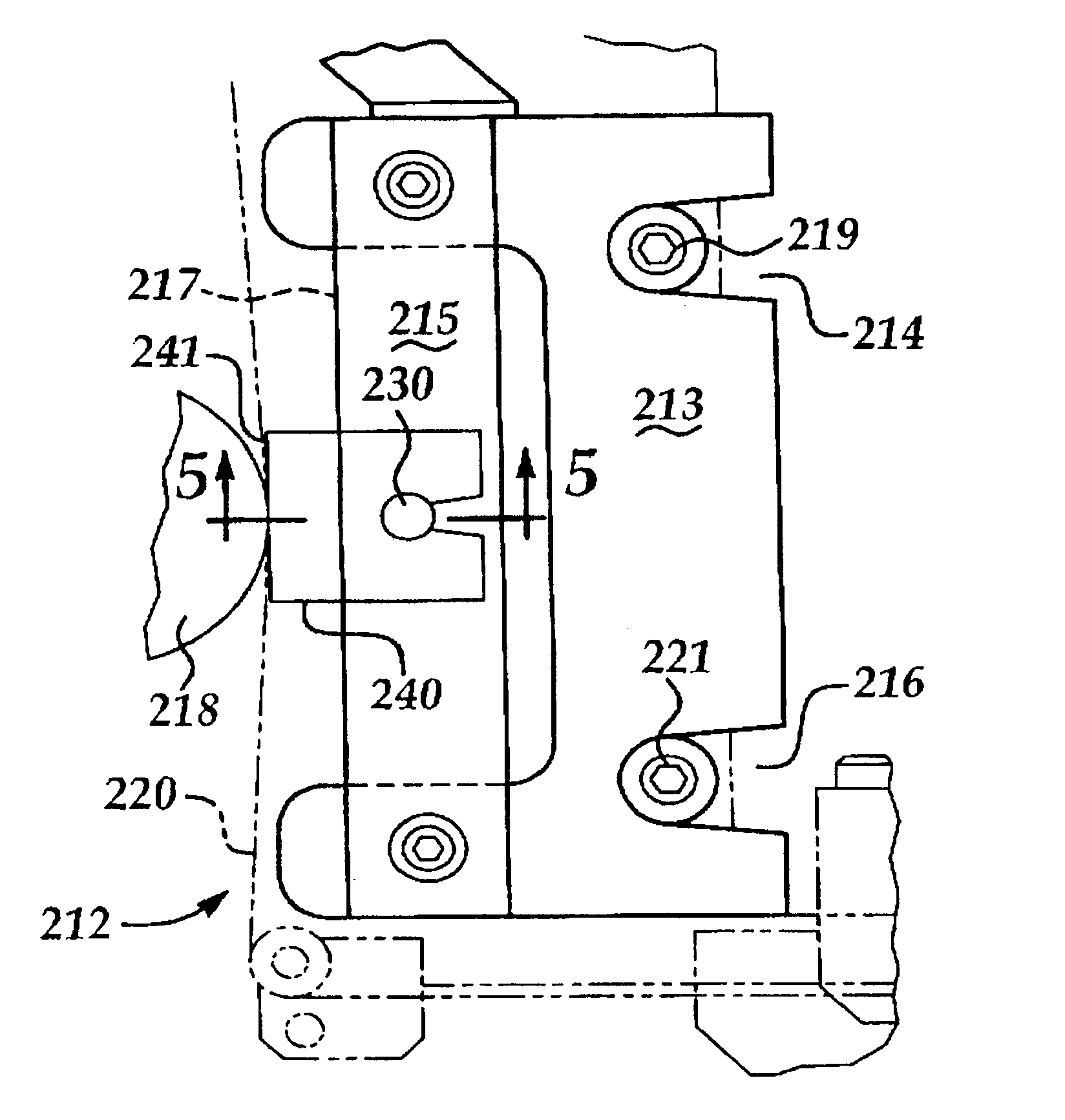
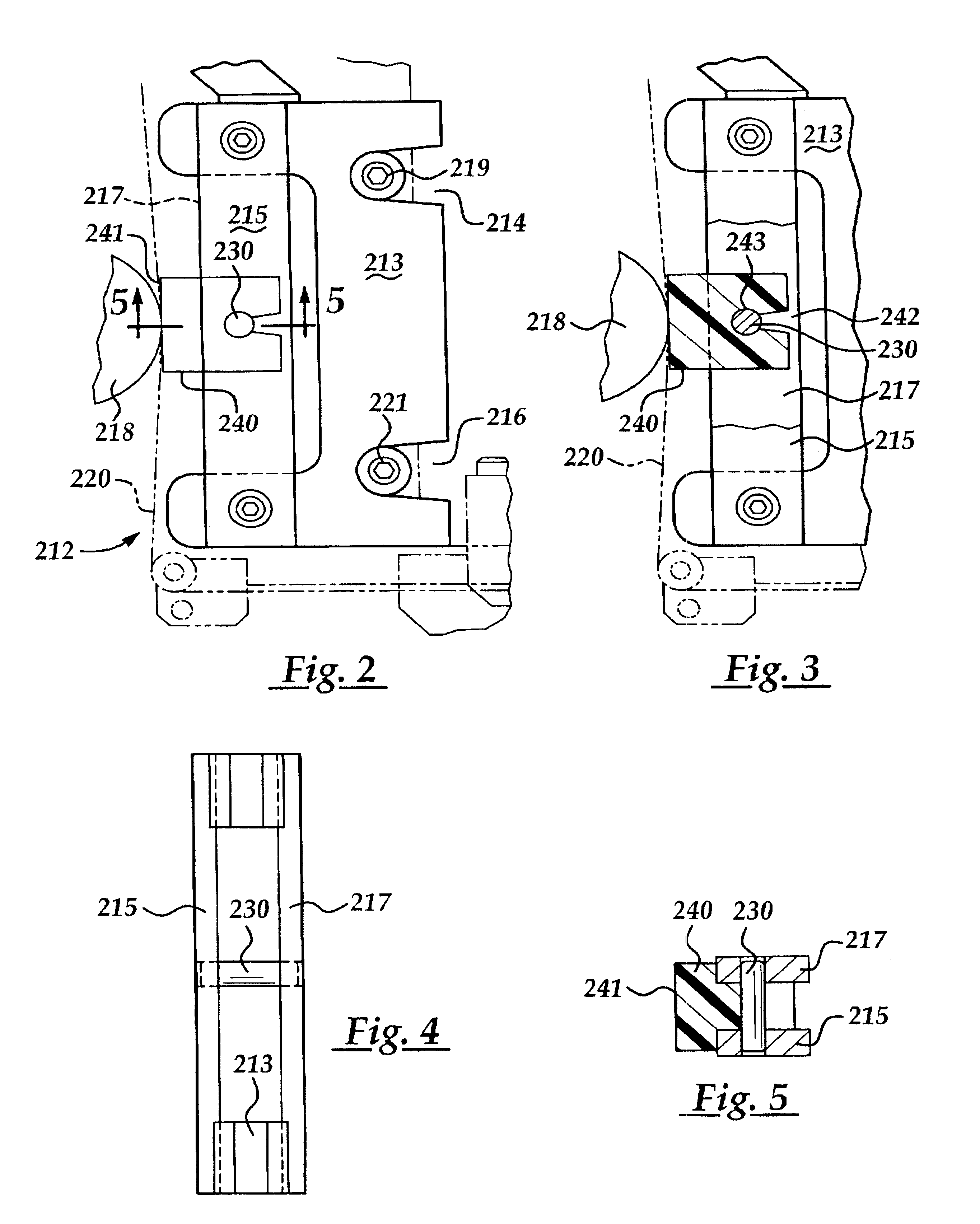
As shown in FIG. 2, an improved shoe 212 is provided for use in a machine similar to that illustrated in FIG. 1. Shoe 212 may be ...


PUM


Abstract

A shoe assembly for a micro-finishing machine for finishing a workpiece includes a C-frame structure adapted for nonrotatable mounting to the micro-finishing machine. The C-frame assembly includes a pair of slats and a replaceable insert secured nonrotatably to the C-frame assembly.

Description

FIELD OF THE INVENTIONThe present invention is related to micro-finishing tooling, and more particularly to a replaceable wear surface insert provided on such tooling for finishing cam lobes for internal combustion engine camshafts.BACKGROUND OF THE INVENTIONU.S. Pat. No. 4,993,191 discloses a tool for micro-finishing cam lobes and is incorporated herein by reference in its entirety. The cam tooling of the '191 patent, typical of prior art finishing tools, includes articulating members to support the film for micro-finishing the cam lobes. As illustrated in FIG. 1 of the '191 patent, rollers 44 are attached to a roller plate 40 by pins 46. The roller plate 40 is held by a support block 36 which is attached to the plates 40 by a pivot pin 42, thereby enabling the roller plates 40 to pivot about the pin 42. The rollers 44 are held by the roller plate 40 with the pins 46 enabling the rollers 44 to rotate. The rollers 44, as shown in FIG. 2 of the '191 patent, support the finishing film...

Claims


Application Information

Patent Timeline
Patent Type & Authority Patents(United States)
IPC IPC(8): B24B21/04B24B35/00B24B19/12B24B21/08B24B19/00
CPCB24B19/12B24B35/00B24B21/08
Inventor MARTIN, III, LEON LEWISLASKO, PETER MICHAELRICO, JAMES ANDREWNADDAF, FADI MAREENDUMAS, JOHN EDWARD
Owner FORD GLOBAL TECH LLC
Why Eureka
Try Eureka