Ink jet printer

a printer and jet technology, applied in the direction of printing, other printing devices, inking devices, etc., can solve problems such as deteriorating print quality

Inactive Publication Date: 2001-11-06
XAARJET
View PDF3 Cites 25 Cited by
  • Summary
  • Abstract
  • Description
  • Claims
  • Application Information

AI Technical Summary

Problems solved by technology

Since a high operating temperature leads to an accelerated ageing process of the ink in and near the a...

Method used


Image

  • Ink jet printer
  • Ink jet printer
  • Ink jet printer

Examples


Embodiment Construction

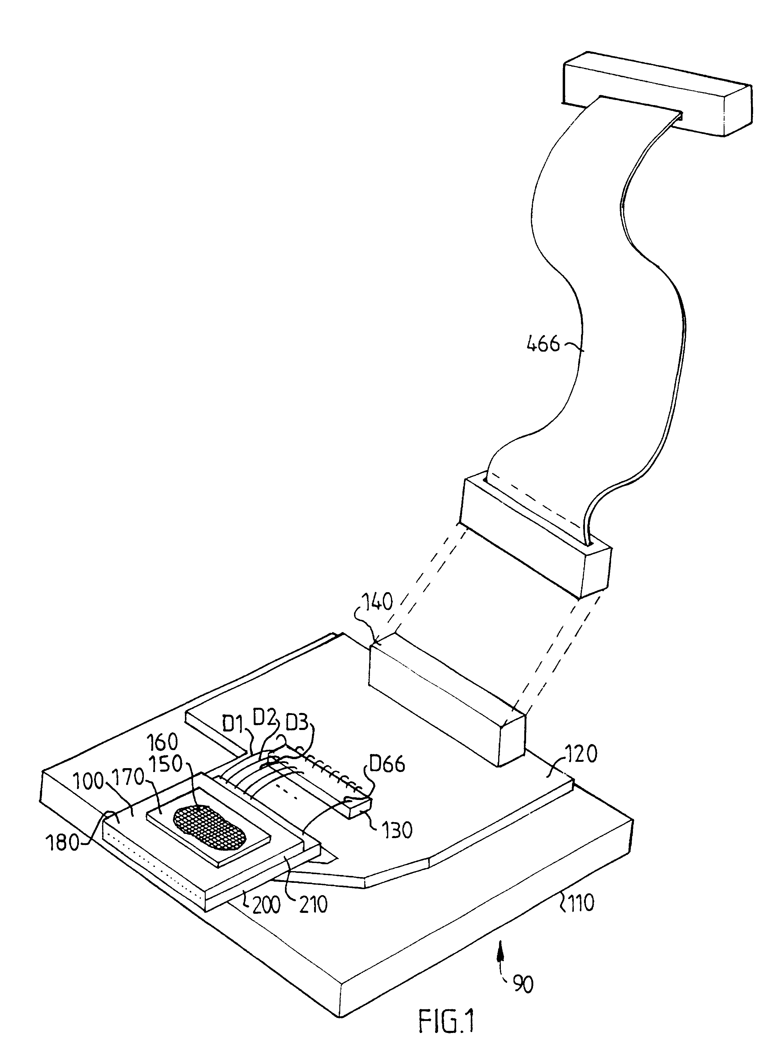
FIG. 1 is a perspective view of a print head arrangement 90 including an ink actuator 100 mounted on a base plate 110. The base plate may be arranged on a shuttle in an ink jet printer (not shown).

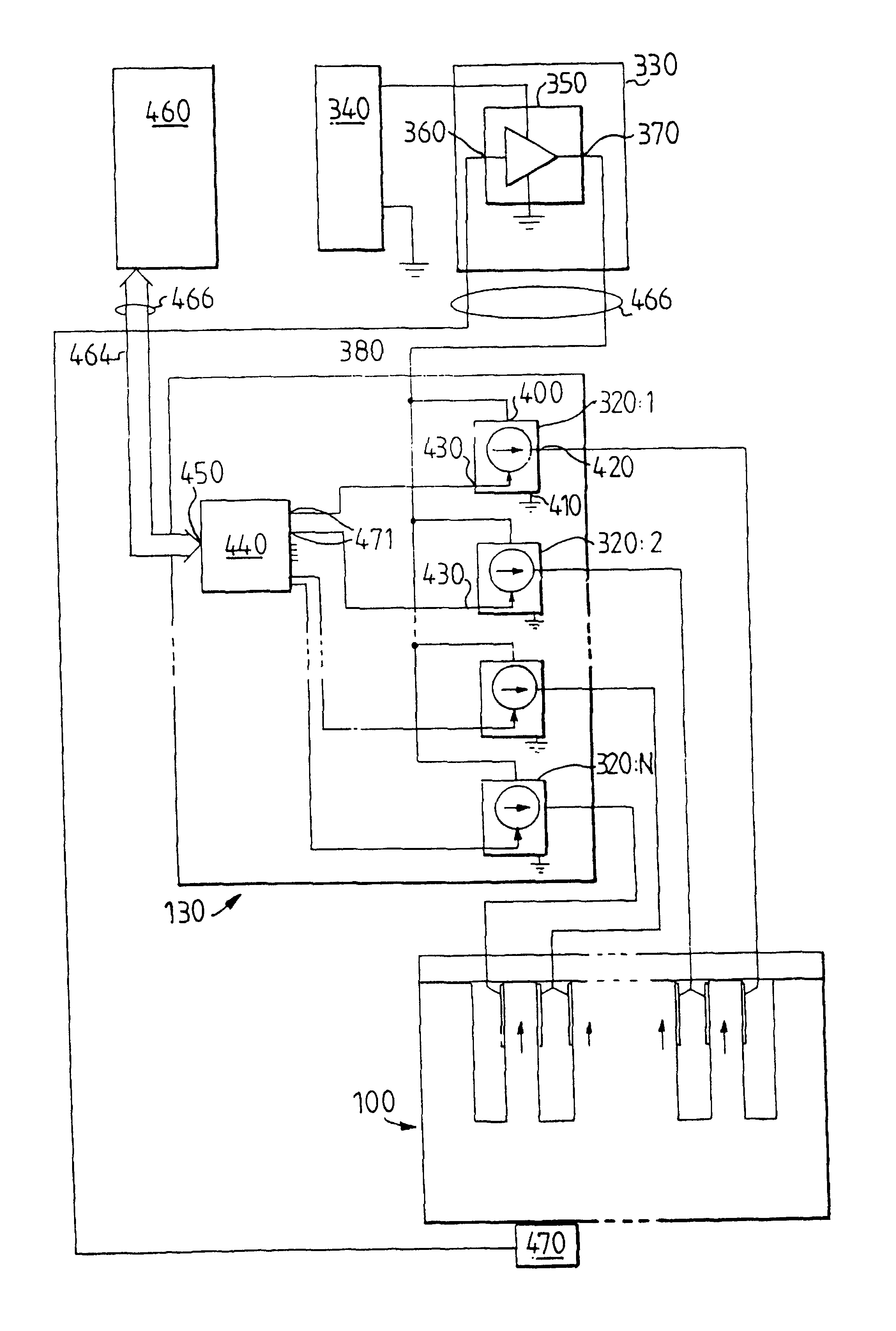
A circuit board 120 is also mounted on the base plate 110. The circuit board 120 includes a control unit 130 and a connector 140.

A central data processing unit in the printer or in a facsimile machine can be connected to the connector 140 and can supply print orders to the connector 140. The print orders thus supplied to the print head arrangement 90 are fed to the control unit 130. The control unit 130 transforms the print orders into electric pulses adapted to cause the actuator assembly 100 to eject ink drops in accordance with the print orders.

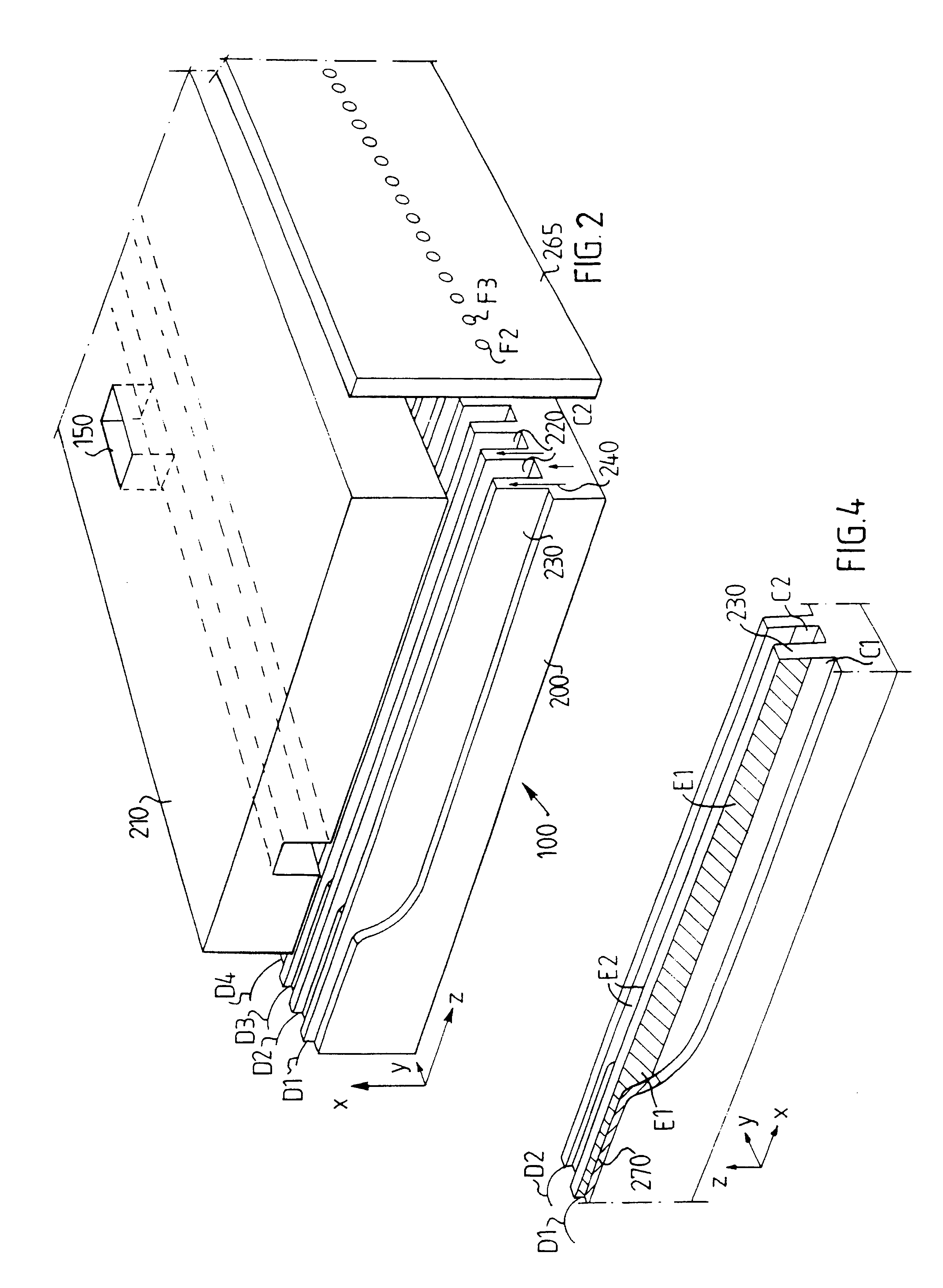
Ink is supplied from an ink reservoir (not shown) to an ink inlet 150 on the actuator assembly 100. The ink inlet 150 may include a filter 160. The ink inlet 150 also includes a sealing unit 170. The sealing unit 170 may include a rubber strip pr...


PUM


Abstract

The invention relates to a droplet deposition apparatus including an ink actuator (100) for ejecting ink droplets; a control unit (130) for controlling droplet formation; and power supply means for supplying a drive voltage to the control unit (130); the drive voltage having a voltage amplitude (V100); the control unit (130) having a plurality of drive signal sources (320) for defining the wave forms of said electric signals; means (470) for detecting at least one performance affecting value; and means (490) for generating an amplitude control signal in response to the performance affecting value; and wherein the power supply means (330) comprises means (350) for adjusting the amplitude of the drive voltage in response to the amplitude control signal; said power supply means being separated from said control unit.

Description

The present invention relates to a droplet deposition apparatus.DESCRIPTION OF RELATED ARTInk jet printers include an ink actuator for ejecting droplets of ink liquid on demand. Such an ink actuator is disclosed in U.S. Pat. No. 5,016,028. The actuator includes a plurality of channels having side walls which are displaceable in response to electric drive signals. When an electric drive signal is applied to a section of the wall, the wall will move, thereby causing the volume of corresponding channels to increase or decrease.U.S. Pat. No. 4,275,402 describes a circuit arrangement for piezoelectric recording nozzles with control circuits providing control voltages to individual nozzles. A regulating circuit includes a temperature-dependent resistor sensing the environmental temperature to effect temperature regulation of the control voltages in accordance with the environmental temperature.U.S. Pat. No. 5,631,675 describes an apparatus for driving an ink jet recording head having piez...

Claims


Application Information

Patent Timeline
IPC IPC(8): B41J2/045B41J2/055
CPCB41J2/04541B41J2/04563B41J2/0457B41J2/04581B41J2/04588B41J2/0459B41J2002/14491B41J2202/10
Inventor DE ROOS, MIKEBOSTROM, CHRISTER
Owner XAARJET
Why Eureka
Try Eureka