Medical ultrasound imaging system with composite delay profile

Inactive Publication Date: 2001-11-06
SIEMENS MEDICAL SOLUTIONS USA INC
View PDF16 Cites 33 Cited by
  • Summary
  • Abstract
  • Description
  • Claims
  • Application Information

AI Technical Summary

Benefits of technology

The preferred embodiments described below use several different types of composite delay profiles that have t

Problems solved by technology

The Axicon focus is typically associated with large side lobe levels that can represent a substantial disadvantage in many clinical applications.
Also, if the probe is limited by regulatory power or thermal limits, then the use of

Method used


Image

  • Medical ultrasound imaging system with composite delay profile
  • Medical ultrasound imaging system with composite delay profile
  • Medical ultrasound imaging system with composite delay profile

Examples


Example

Turning now to the drawings, FIGS. 1 through 5 illustrate components of ultrasonic imaging systems that can be used to implement the present invention, and FIGS. 6b through 13b provide information regarding composite delay profiles of selected embodiments of this invention.

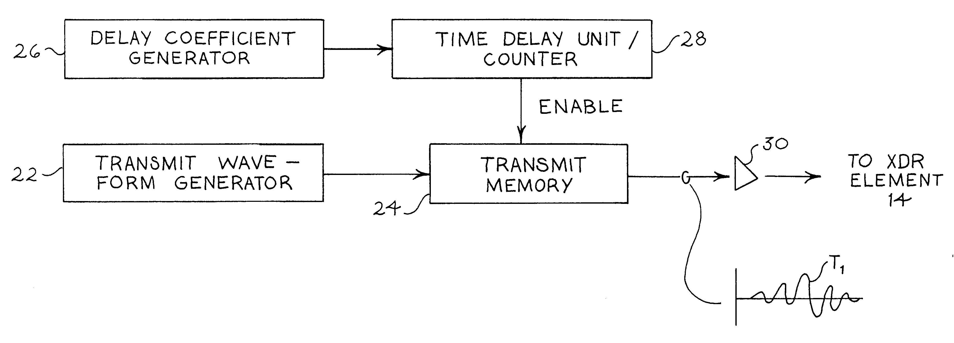
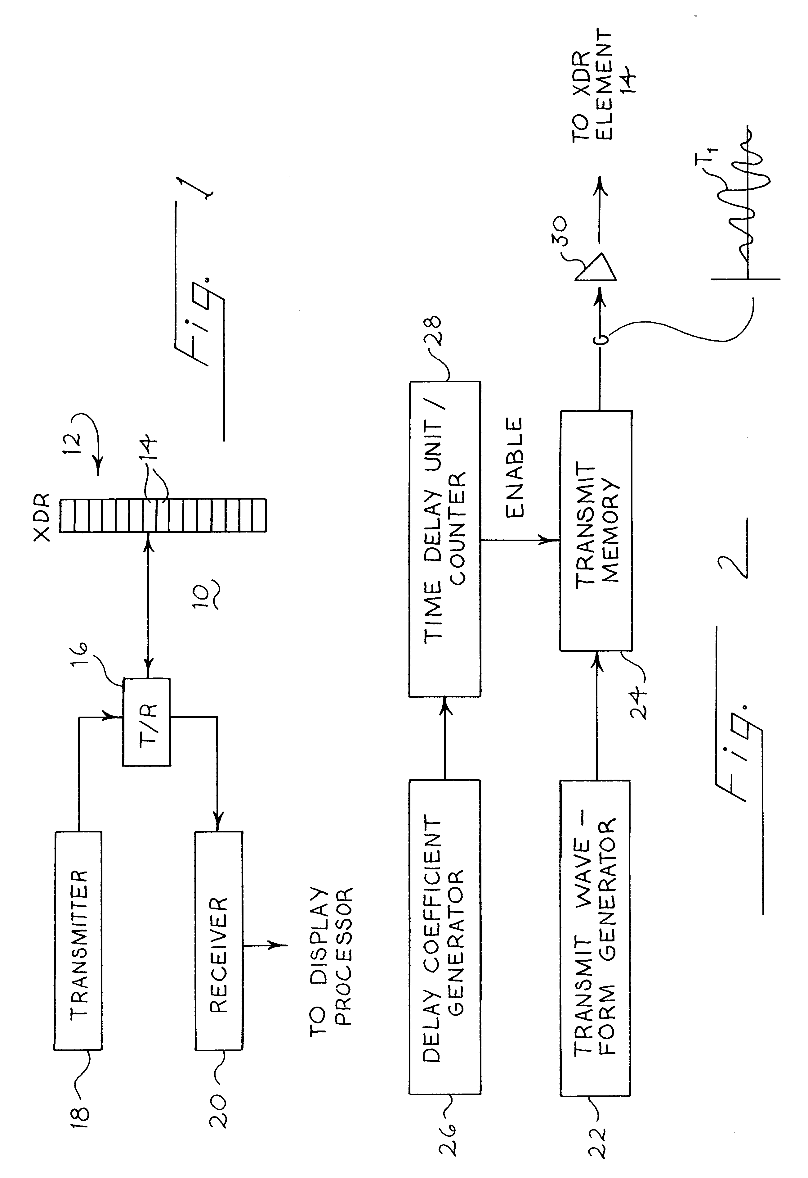
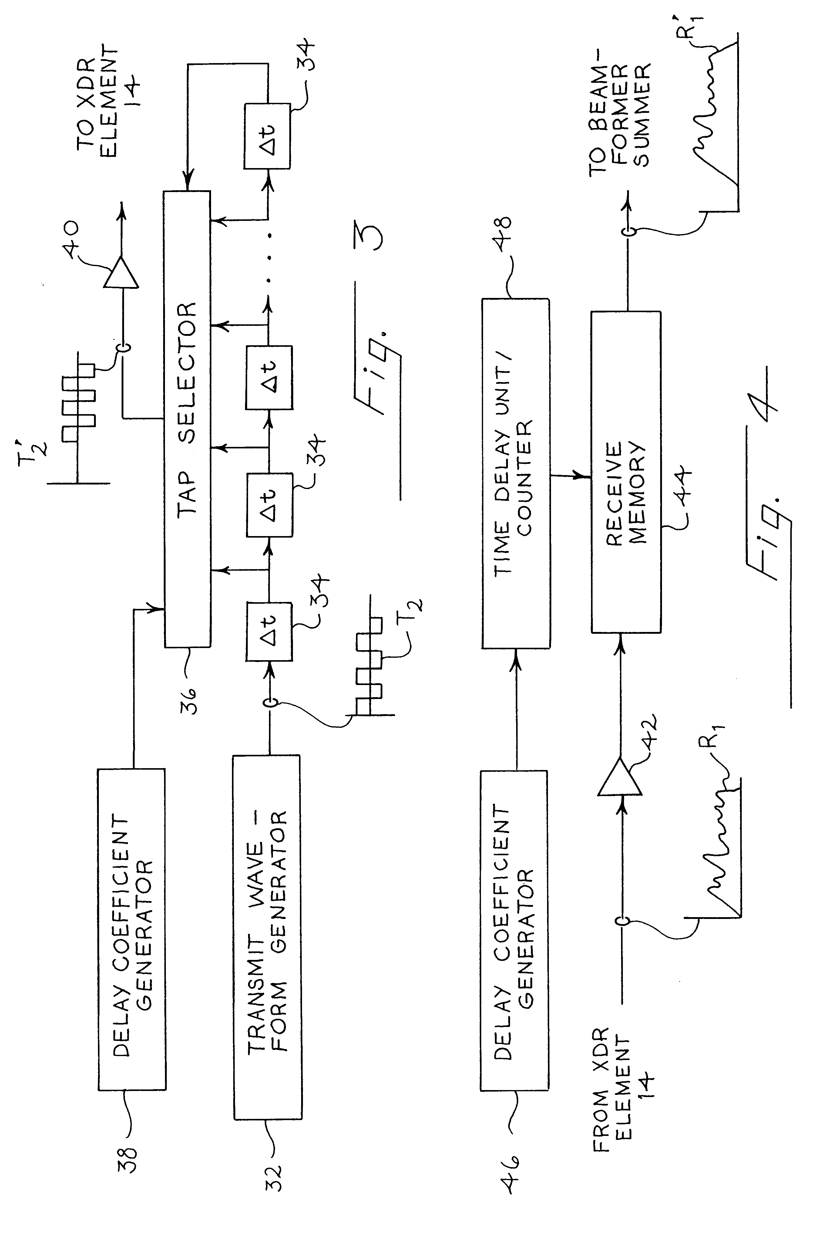
As shown in FIG. 1, a medical diagnostic ultrasonic imaging system 10 includes a transducer probe 12 that in turn includes an array of individual transducer elements 14. The transducer probe 12 is connected by a transmit / receive switch 16 to a transmitter 18 and a receiver 20. The transmitter 18 applies respective transmit waveforms to the individual transducer elements 14 to cause the transducer probe 12 to form an ultrasonic transmit beam which is directed into an imaged region. Echoes from the imaged region impinge in the transducer elements 14, causing the transducer elements 14 to generate receive waveforms that are delayed and summed in the receiver 20 to form receive beams along desired receive lines. These...


PUM


Abstract

A medical ultrasound diagnostic imaging system includes a delay system that applies a composite delay profile to signals to or from respective transducer elements. One composite delay profile includes a first, substantially point-focus delay profile for a first set of the transducer elements and a second, substantially point-focus delay profile for a second set of the transducer elements. The first and second delay profiles cause ultrasonic energy from the respective first and second sets of the transducer elements to constructively add at first and second respective spaced focal zones in either transmit or receive. Another composite delay profile includes first and second portions that substantially correspond to respective parts of a point-focus delay profile, and third and fourth portions that are intermediate the point-focus delay profile and respective tangents.

Description

This invention relates to medical ultrasound diagnostic imaging, and in particular to systems and methods for providing more effective focusing of ultrasound waveforms.In current ultrasound imaging systems, transducer probes which include many individual transducer elements are operated as phased arrays.Delay profiles are applied either to transmit waveforms or to receive waveforms associated with individual transducer elements in order to achieve desired focusing characteristics. One prior-art approach is to use a simple delay profile in which all of the transducer elements of the transducer probe are focused at a single focal point. Another prior-art approach is to use a delay profile that provides a distributed focus, as for example the well-known Axicon profile that provides a line focus.A third prior-art approach is to transmit two or more transmit focal zones simultaneously. This is typically done by superimposing two separate delay profiles such that each transducer element g...

Claims


Application Information

Patent Timeline
IPC IPC(8): G10K11/00G10K11/34
CPCG10K11/346
Inventor BOLORFOROSH, MIRSAIDCHOU, CHING-HUAGEE, ALBERTHUANG, SUNGRUNGUSTUNER, KUTAY
Owner SIEMENS MEDICAL SOLUTIONS USA INC
Why Eureka
Try Eureka