Method for making a multi-piece crankshaft

a multi-piece, crankshaft technology, applied in the field of crankshafts, can solve the problems of increasing the overall material cost of the previously known one-piece crankshaft, disadvantages of one-piece crankshafts, and requiring specialized and expensive equipmen

Inactive Publication Date: 2001-11-13
DONALD G LEITH
View PDF31 Cites 24 Cited by
  • Summary
  • Abstract
  • Description
  • Claims
  • Application Information

AI Technical Summary

Benefits of technology

Thereafter, in one embodiment of the invention counterweights, which may be constructed of an inexpensive material, are positioned around each end of the crankpin at its junction with the main shaft. These counterweights are then secured to the crankpin and main shaft in any conventional fashion thereby completing the crankshaft.
Although preferably the portion of the main shaft between the ends of the crankpin is removed prior to attaching the counterweights around the ends of the crankpin and the main shaft, the counterweights may alternatively be secured to the crankpins and main shaft prior to removing the portion of the main shaft between the ends of the crankpin.

Problems solved by technology

The previously known one-piece crankshafts, however, are disadvantageous in several different respects.
One disadvantage of the previously known one-piece crankshafts is that the casting process and subsequent machining of the casting is a relatively expensive process requiring specialized and expensive equipment.
A still further disadvantage of the previously known one-piece crankshafts is that, since the crankshaft is formed from a one-piece casting, the entire casting must be made from the same material.
This disadvantageously increases the overall material cost for the previously known one-piece crankshafts since the crankpins and main shaft must be constructed from a high strength steel while, conversely, it is unnecessary to construct the counterweights from a high strength material.
A still further disadvantage of the previously known one-piece crankshafts is that, in order to connect the piston rod to the crankpin, the connecting rod must necessarily utilize a split ring connector, i.e. two semi-circular shells which are secured together, typically by bolts.
Such split ring connectors for the piston rods are necessarily more expensive than a single piece connector for a piston rod.
As a practical matter, it has not been possible to manufacture these multi-piece crankshafts with the small manufacturing tolerances required by certain applications on a consistent and cost effective basis.
In particular, it is extremely difficult to maintain the concentricity of the segments of the main shaft during the attachment of the counterweights and crankpin.
Likewise, it has proven impractical to maintain the parallelism between the axis of the crankpin and the main shaft where small manufacturing tolerances are required.

Method used


Image

  • Method for making a multi-piece crankshaft
  • Method for making a multi-piece crankshaft
  • Method for making a multi-piece crankshaft

Examples


Embodiment Construction

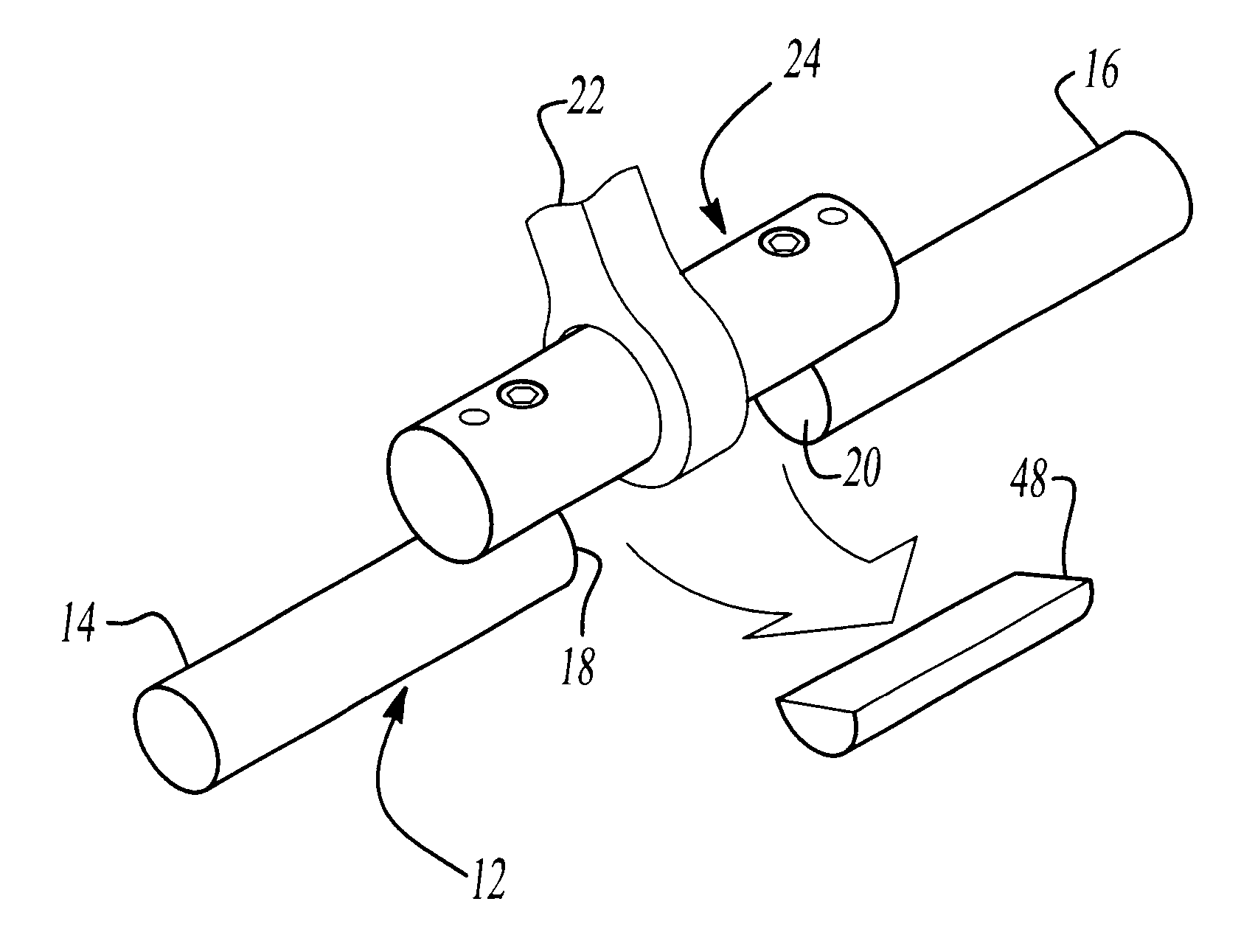
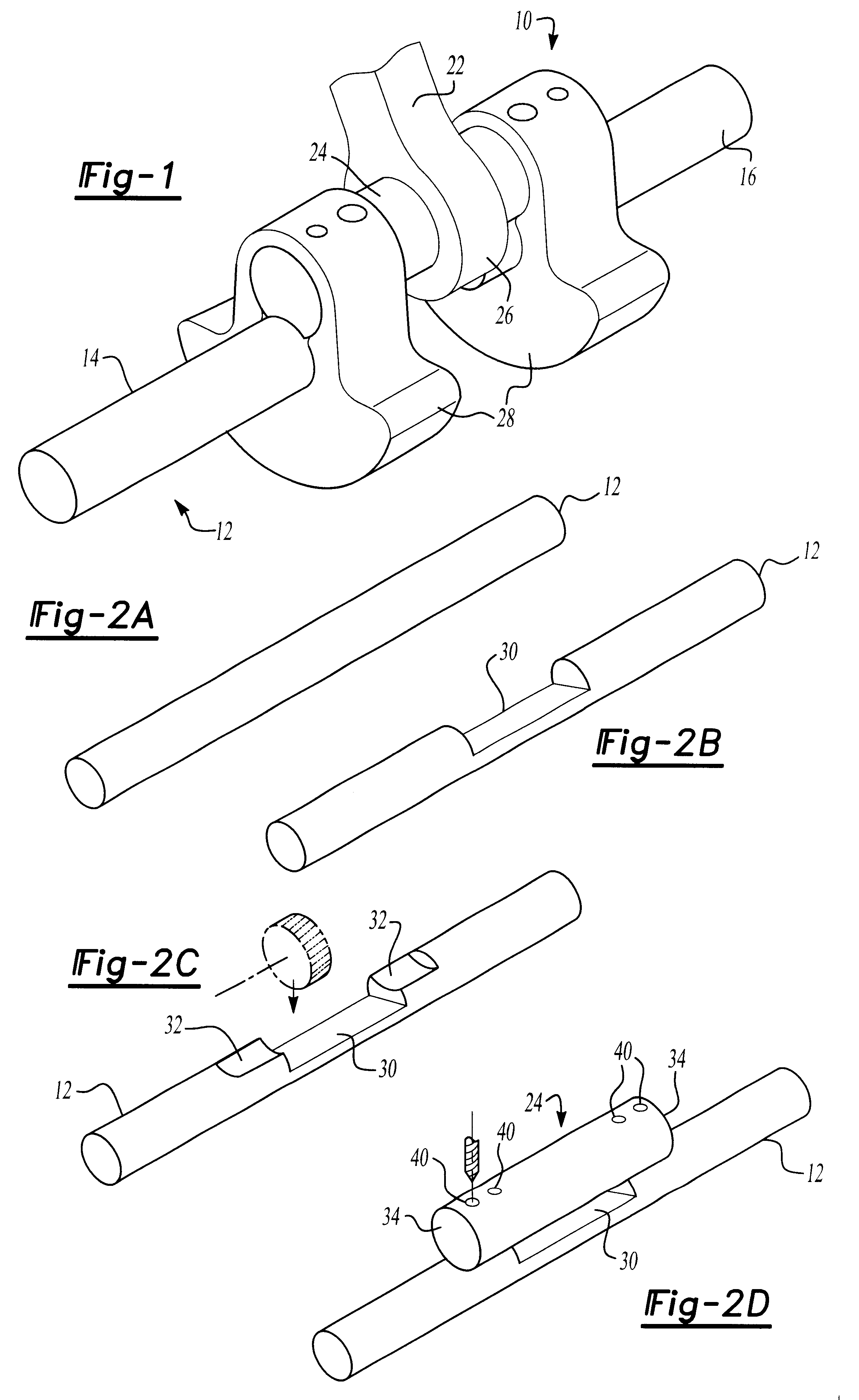
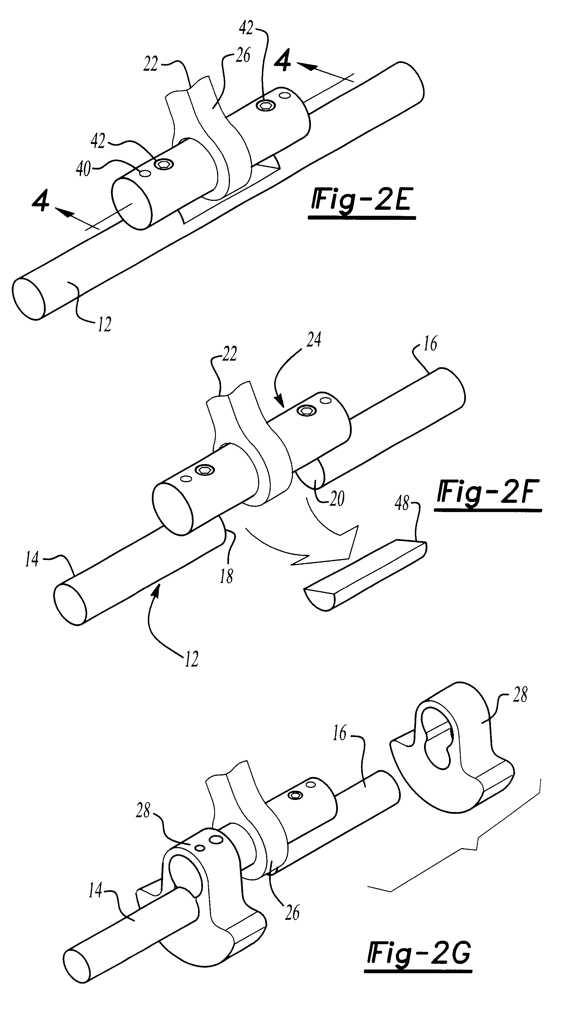
With reference first to FIG. 1, a completed crankshaft 10 constructed by the method of the present invention is illustrated in FIG. 1. The crankshaft 10 includes a main shaft 12 having two or more axially aligned main shaft segments 14 and 16. Each main shaft segment 14 and 16, furthermore, has two facing ends 18 and 20 (FIG. 3). These facing ends 18 and 20 of the main shaft segments 14 and 16, respectively, are axially spaced apart from each other by a distance sufficient to allow a connecting rod 22 to pass between the ends 18 and 20 of the main shaft segments 16 and 14.

Still referring to FIG. 1, a crankpin 24 extends across the ends 18 and 20 of the main shaft segments 14 and 16, respectively, and is secured to the shaft segments 14 and 16 in a manner to be subsequently described in greater detail. The axis of the crankpin 24 is parallel to but radially spaced from the axis of the shaft segments 14 and 16. Furthermore, the piston connecting rod 22 includes a bearing 26 disposed a...


PUM

PropertyMeasurementUnit
strengthaaaaaaaaaa
longitudinal lengthaaaaaaaaaa
lengthaaaaaaaaaa

Abstract

A method for making a multiple piece crankshaft from a shaft and a crankpin is disclosed. A notch is first machined on an intermediate section of the shaft such that the notch has a length slightly less than the length of the crankpin. Mating surfaces are then formed on the shaft at opposite ends of the notch. Thereafter, the crankpin is positioned on the mating surfaces on the shaft so that the crankpin is parallel to and spaced from an axis of the shaft. The ends of the crankpin are then secured to the mating surfaces formed on the crankshaft and a portion of the intermediate section of the shaft is then removed by machining. A counterweight is finally positioned over each end of the crankpin at its juncture with the main shaft and secured to the crankpin and shaft thereby forming the crankshaft. Alternatively, the crankpin is positioned on mating surfaces formed on the counterweights and fasteners then secure the crankpin, counterweights and main shaft together.

Description

I. Field of the InventionThe present invention relates generally to crankshafts and, more particularly, to a method for making a multi-piece crankshaft.II. Description of the Prior ArtCrankshafts of the type used in reciprocal piston engines and compressors typically comprise a main shaft having at least two axially aligned shaft sections with a crankpin extending between the facing ends of the shaft sections. The crankpin is oriented so that its axis is parallel to, but radially spaced from, the axis of the main shaft. Counterweights are then provided at the junction of each end of the crankpin with the main shaft thus forming the crankshaft.There have been many different ways for manufacturing the previously known crankshafts. In one conventional method, the entire crankshaft is formed as a one-piece casting. After forming the casting, the casting is machined, typically by grinding, in order to form the crankshaft.The previously known one-piece crankshafts, however, are disadvanta...

Claims


Application Information

Patent Timeline
Patent Type & Authority Patents(United States)
IPC IPC(8): F16C3/04F16C3/10
CPCF16C3/10B23P2700/07Y10T74/2177Y10T29/49293Y10T29/17Y10T29/49286Y10T29/49799
Inventor LEITH, DONALD G.
Owner DONALD G LEITH
Why Eureka
Try Eureka