
Peak flow meter

a flow meter and meter technology, applied in the field of peak flow meter, can solve the problems of equipment sensitivity, device not being sensitive enough for some objects, and further affecting sensitivity

Inactive Publication Date: 2001-11-13
FORD THOMAS MCDONALD
View PDF4 Cites 17 Cited by
  • Summary
  • Abstract
  • Description
  • Claims
  • Application Information

AI Technical Summary

Benefits of technology

In addition to the disadvantages ascribed to the U.S. Pat. No. 4,292,853 arrangement, the affect of the magnets mounted on the radial arms is to increase the mass of the rotor, thus increasing inertia and decreasing sensitivity.
It is a yet further object of the invention to provide an air-flow measuring device which is easily cleaned or sterilised.
It will be seen that by applying an air-flow which is changed from a direction parallel to the rotational axis of the blade, firstly to a direction where the major force component is perpendicular to said axis but in the opposite sense and subsequently reversing the sense (to build back-pressure), before finally being angularly deflected to impinge on the blades, facilitates the use of blade means having low inertial properties. The use of such a blade means allows for an extremely sensitive air-flow valve to be realised.
The air-flow valve of the invention is ideally suited for use in an air-flow measuring device, and preferably includes mans for releasably securing the valve to such a device. The valve is made from a number of easily assembled and disassembled components thus facilitating cleaning. The valve components preferably comprise plastics material or other suitable material to withstand regular sterilisation.

Problems solved by technology

The inertia of the spring-loaded device will affect the sensitivity of the equipment and may require that, for a valid measurement, a degree of force is needed which a severe asthmatic, or an otherwise respiratory-impaired individual, cannot provide.
Again the device may not be sensitive enough for some objects.
In addition the difficulty in accurately measuring the degree of cooling further affects the sensitivity.
Turbines generally are heavy for their size and do not provide the required sensitivity.
In use, this arrangement suffers the disadvantage of developing a significant back-pressure in the device which is undesirable as it adversely affects the sensitivity and efficiency of the device.
If back-pressure in a device is too low, a poor indication of vital capacity is received.
Conversely, if back-pressure is too high, subjects having poor lung function will be unable to provide sufficient force to operate the device.
Sensitivity of the device will also be adversely affected.
High inertia results in slow acceleration of the blades and a continuation of rotation after the applied exhilation ceases will result.
One problem associated with prior art devices is the exposure of the blades to moisture or sputum carried on the exhaled breath.
A build-up of such deposits on the blade will naturally affect its inertia and consequently, the accuracy of the device.
Devices where the breath is applied directly to the blades or where the air-flow is re-directed marginally to impinge the blades are particularly vulnerable.
Where optical means are provided to measure device parameters, the deposits mentioned above also have a deleterious affect.
Firstly, the inertia of the rotor which is connected to a gearbox limits the allowable sensitivity and could not be used for accurate peak flow measurement.
Secondly, air flow from the inlet can directly impinge the rotor allowing food particles, sputum or excessive vapour to adhere thereto.
Additionally, the construction disclosed does not allow for easy disassembly and cleaning.
In addition to the disadvantages ascribed to the U.S. Pat. No. 4,292,853 arrangement, the affect of the magnets mounted on the radial arms is to increase the mass of the rotor, thus increasing inertia and decreasing sensitivity.

Method used


Image

  • Peak flow meter
  • Peak flow meter
  • Peak flow meter

Examples


Embodiment Construction

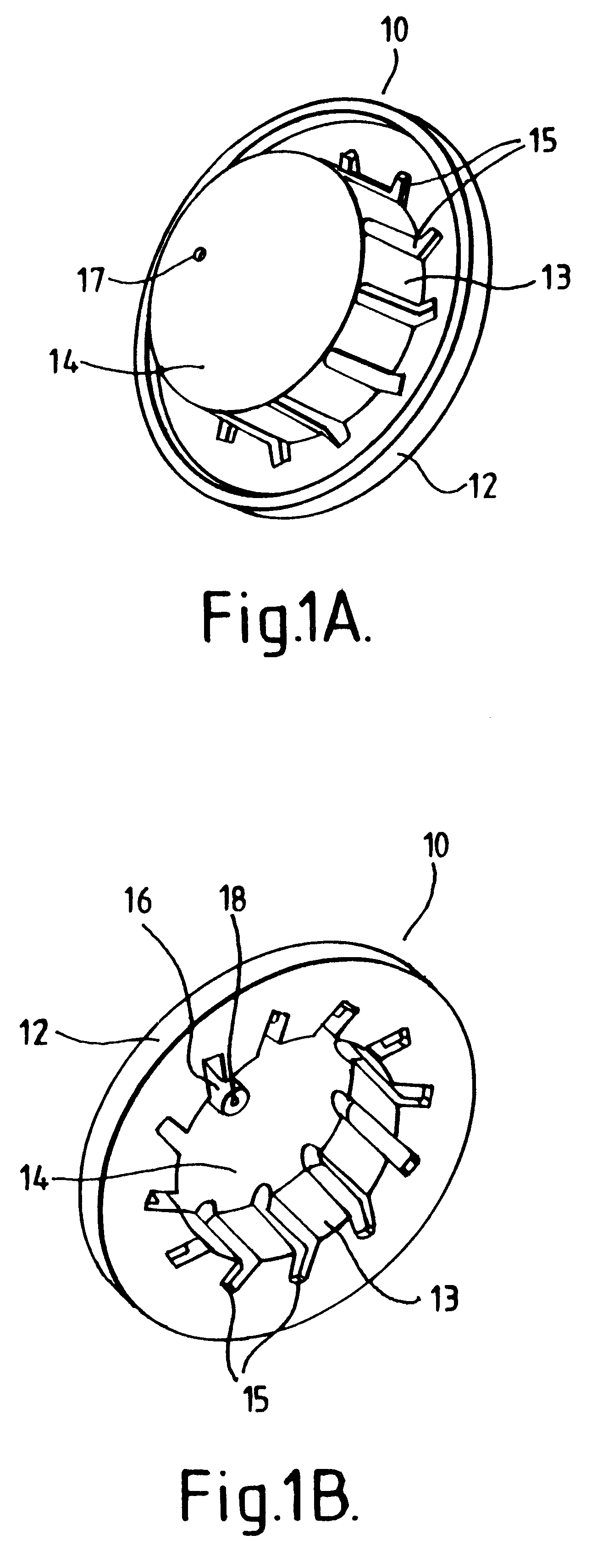
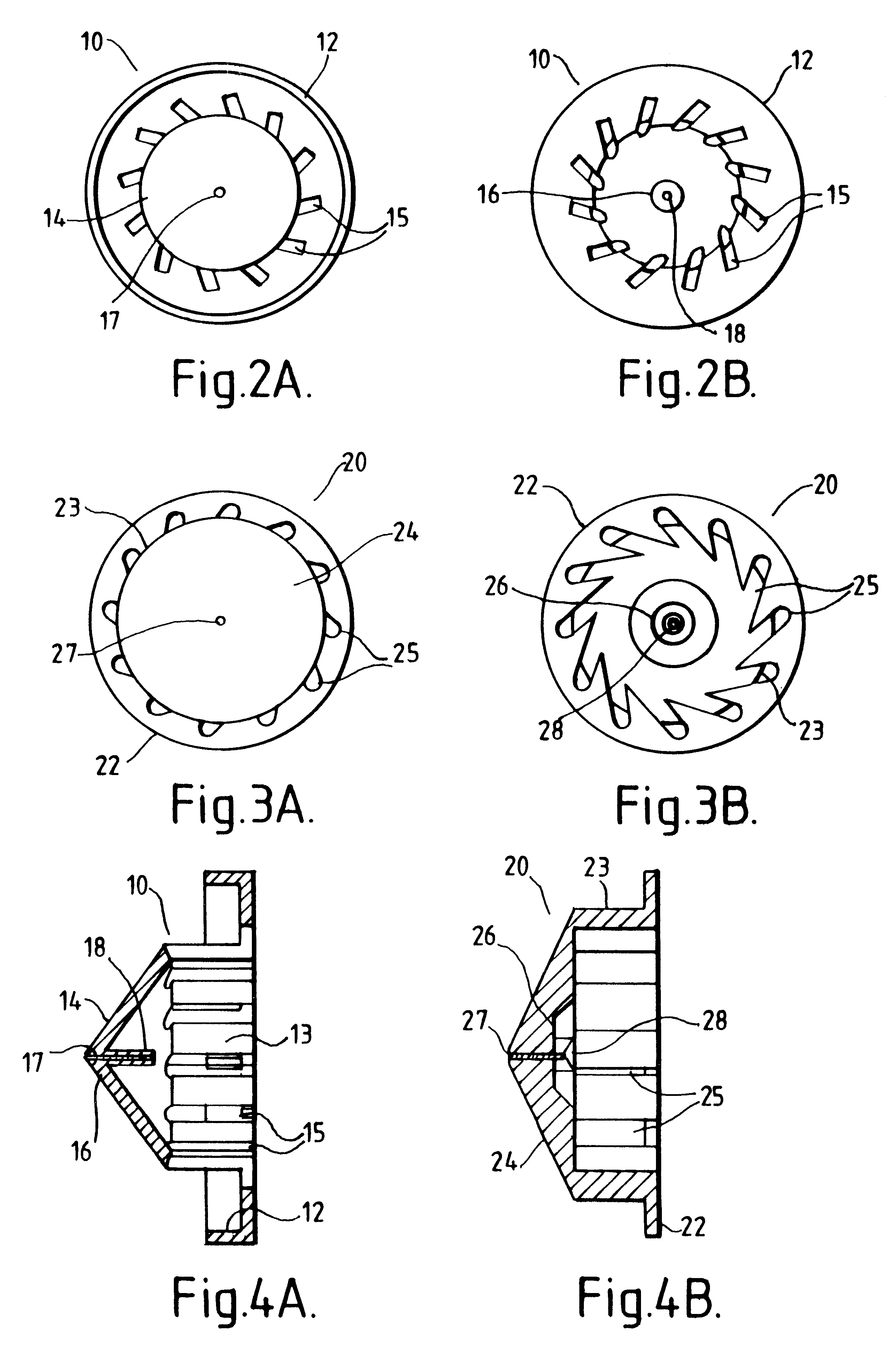
Referring to the drawings and initially to FIGS. 1A and 1B, the air-flow valve of the invention comprises a first arrangement of stator 10 consisting of a hat-shaped body having a rim 12, a riser 13 and an upper region 14 which is conical.

Air-directing apertures 15 are provided in the riser 13. A rotor bearing 16 is provided at the apex of the conical upper region 14 and comprises a screw adjuster 17 and spindle seat 18.

FIGS. 1A, 1B, 2A and 2B show more particularly the positioning of the apertures 15 in the first arrangement of stator 10, the apertures 15 being equi-spaced around the periphery of the riser 13. The apertures 15 extend the height of the riser 13 and extend also towards the rim 12, as shown in FIGS. 2A and 2B. The apertures 15 are angled axially so as to efficiently direct air-flow. Alternative forms of stator, for example, where the apertures extend towards the rim by means of upstanding fins or flaps (FIGS. 11 and 12), will be described hereinafter.

A second arrangem...


PUM


Abstract

An air-flow measuring device for measuring respiratory performance includes a valve having at least one rotary blade for detecting air-flow through the device. The valve includes at least one air-directing aperture which alters the direction of air-flow incident on said valve from a first direction onto a second altered direction. The second direction is perpendicular to the first direction and to the planar surface of the rotary blade. The direction-altered air-flow provides a force which causes the rotary blade to move. An optical transducer measures the rotation of the blade to determine air-flow parameters in the device.

Description

This invention relates to the field of apparatus for measuring lung function. Particularly, the present invention relates to an air-flow valve for measuring the volume of air which can be expelled from the lungs and to a device incorporating such a valve to give improved indication of lung function.BACKGROUND TO THE INVENTIONDuring normal adult respiration, the amount of air inspired or expired per breath (tidal air) is approximately 500 ml.After a normal tidal expiration, a further volume of air (the expiratory reserve-volume) can be expired--approximately 750-1000 ml in adults.Vital capacity is the maximum volume of air which can be expelled from the lungs by a forceful effort, following a deliberate inhalation of the maximum volume possible. This vital capacity is normally of the order of 4.8 liters in men and 3.2 liters in women, but can be substantially reduced in asthmatics and people with other bronchial problems. The vital capacity and / or the ability to exhale thus provides ...

Claims


Application Information

Patent Timeline
IPC IPC(8): A61B5/087A61B5/09A61B5/08
CPCA61B5/0873A61B5/09
Inventor FORD, THOMAS MCDONALD
Owner FORD THOMAS MCDONALD
Learn More