Piston cylinder unit with a movement determination device

Inactive Publication Date: 2001-11-20
ZF FRIEDRICHSHAFEN AG
View PDF19 Cites 27 Cited by
  • Summary
  • Abstract
  • Description
  • Claims
  • Application Information

AI Technical Summary

Problems solved by technology

Although this device is purported to be suitable for so-called single-tube vibration dampers, this assertion is difficult to confirm because single-tube vibration dampers have a separating piston that separates a compensation space from the working space remote from the piston rod.
This cre

Method used


Image

  • Piston cylinder unit with a movement determination device
  • Piston cylinder unit with a movement determination device
  • Piston cylinder unit with a movement determination device

Examples


Embodiment Construction

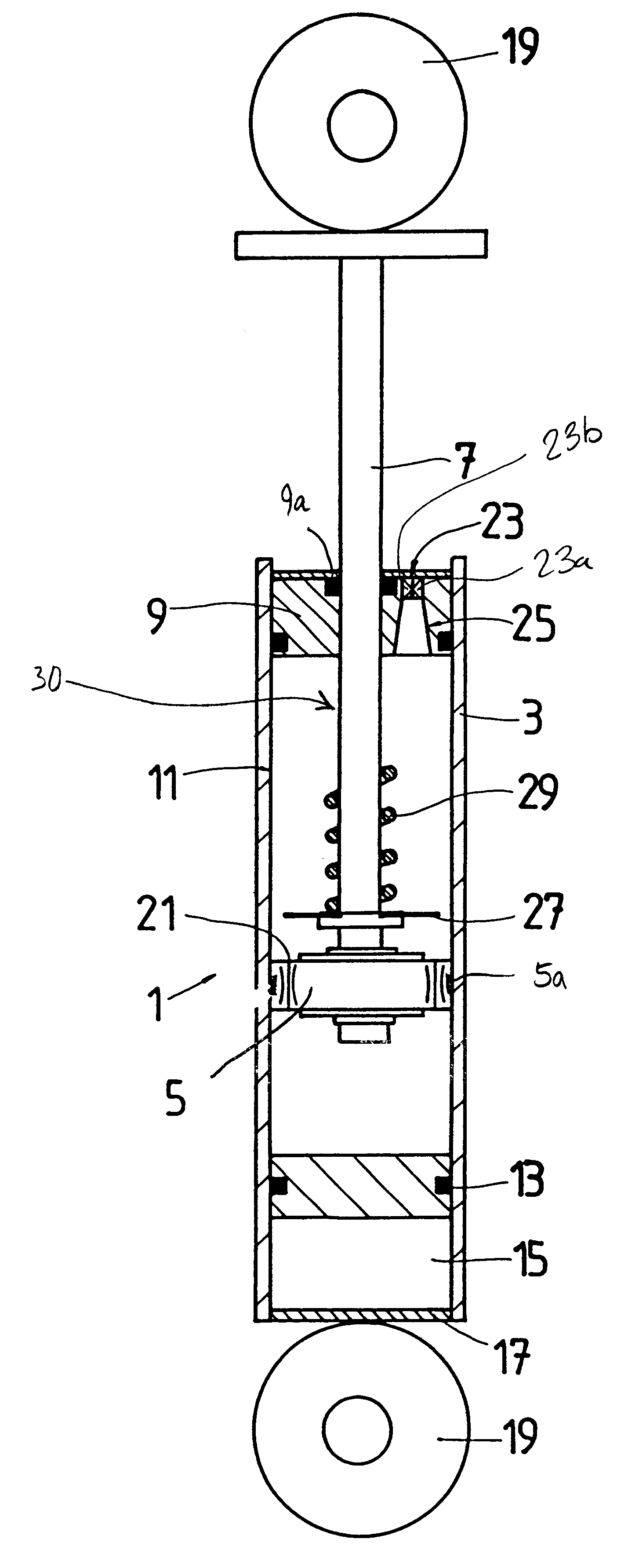
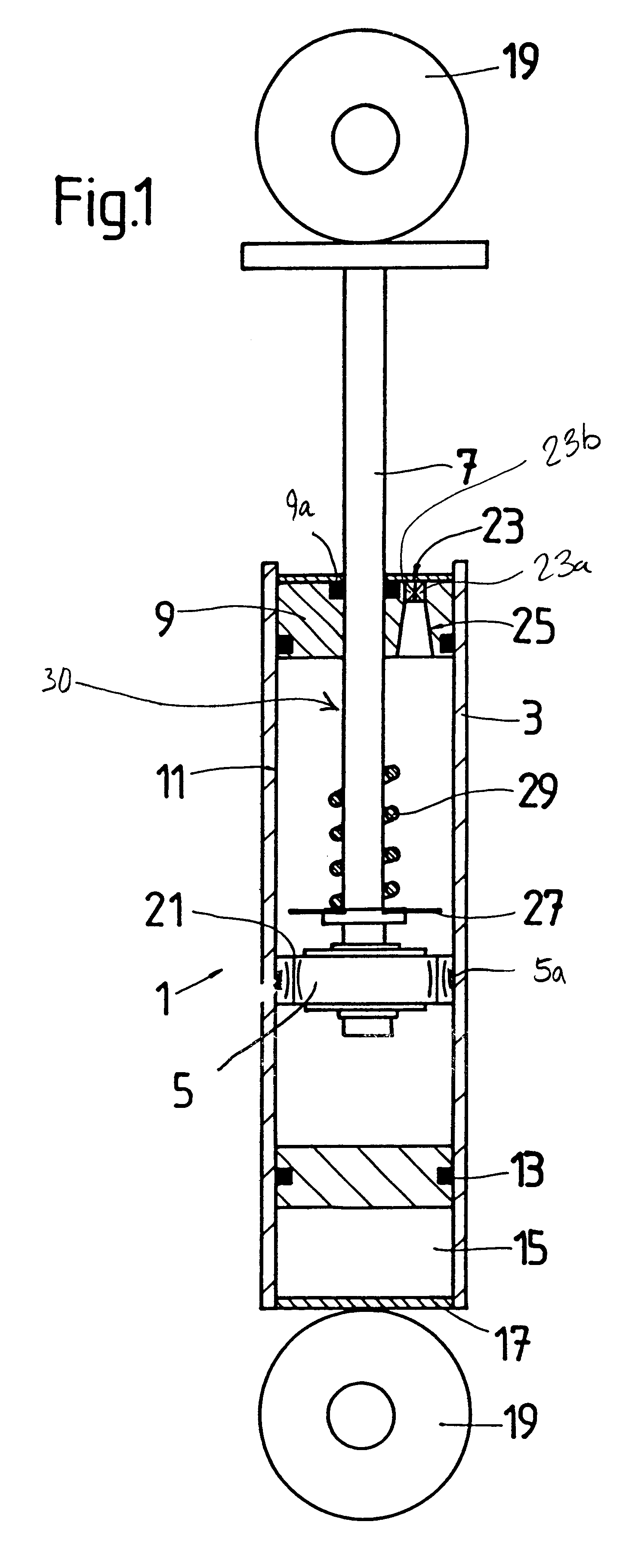
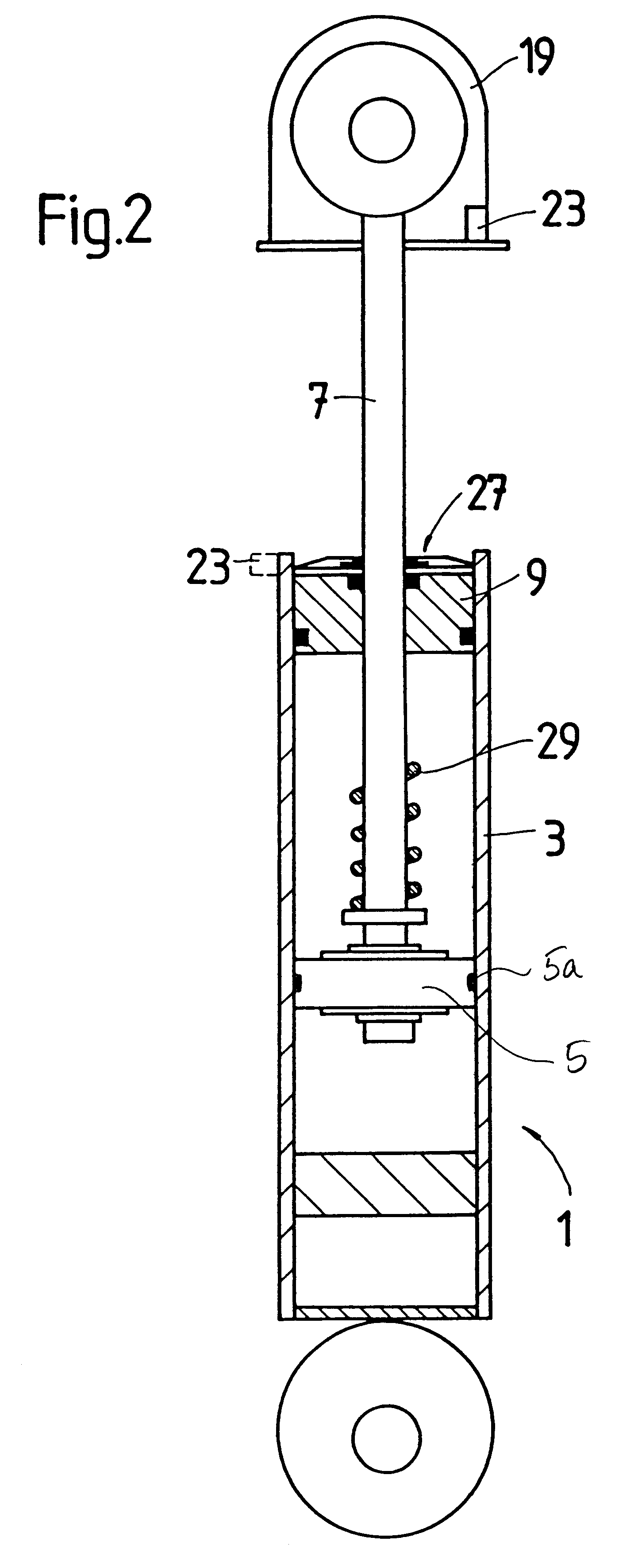
FIG. 1 shows, for example, a piston-cylinder unit 1 in the embodiment of a one-tube vibration damper. However, the invention may also be used, in principle, in other applications.

The piston-cylinder unit 1 includes a cylinder 3 in which a piston 5 connected to a piston rod 7 is arranged in an axially movable fashion. The ends of the cylinder 3 are closed by a piston rod guide 9 at one end through which the piston rod 7 exits the cylinder 3 and a bottom 17 at the other end connected to an eye 19. The piston rod guide 9 closes a working space 11 of the cylinder 3 filled with damping medium and separated by a separating piston 13 from a gas space 15, which is closed by the bottom 17.

Upon movement of the piston rod 7, the damping medium in working space 11 is forced through damping valves 21 in the piston 5. A piston ring (not shown) prevents the damping medium from flowing laterally around the piston 5.

A movement determination device 23 is arranged Inside the piston rod guide 9. The mo...


PUM


Abstract

A piston-cylinder unit includes a cylinder with a piston rod guide and a piston rod with a piston axially movably mounted in the cylinder so that the piston rod runs through a hole in the piston rod guide. A movement determination device comprising a transmitter portion and a receiver portion determine the movement of the piston from the travel time of waves generated by the transmitter portion. The movement determination device is arranged inside the piston rod guide, and waves reflected by the piston-piston rod component group are analyzed to determine the movement of this component group.

Description

1. Field of the InventionThe invention relates to a movement determination device for determining movement between two movable parts in a piston-cylinder unit.2. Description of the Related ArtGerman reference DE 40 41 407 C2 describes a device for detecting the relative speeds of a piston and cylinder of a vibration damper. The device discloses a sound generator and a sound pickup arranged in the working space of the cylinder remote from the piston rod of the vibration damper. The bottom of the cylinder, specifically the bottom valve, serves as the reflection surface for reflecting the transmitted sound. Although this device is purported to be suitable for so-called single-tube vibration dampers, this assertion is difficult to confirm because single-tube vibration dampers have a separating piston that separates a compensation space from the working space remote from the piston rod. This compensation space--and thus the separating piston--must compensate for the volume of the in-and-...

Claims


Application Information

Patent Timeline
IPC IPC(8): B60G17/019B60G17/015F16F9/32F16F9/00F16F9/06
CPCB60G17/01933F16F9/061F16F9/3242B60G2202/154B60G2204/112B60G2400/252B60G2401/176F16F2230/08
Inventor LUTZ, DIETERTHOMA, ACHIM
Owner ZF FRIEDRICHSHAFEN AG
Why Eureka
Try Eureka