
Airport and runway laser lighting method

a technology for airports and runways, applied in landing aids, instruments, aircraft traffic control, etc., can solve problems such as inability to achieve, poor visibility, and often difficult to achieve, and achieve the effect of improving visibility, simplifying the task of landing, and prolonging visibility

Inactive Publication Date: 2001-11-20
REASON RICHARD E
View PDF8 Cites 20 Cited by
  • Summary
  • Abstract
  • Description
  • Claims
  • Application Information

AI Technical Summary

Benefits of technology

It is an object of this invention to disclose an improved method of illuminating airports and runways. A method is disclosed using laser light which is much better able to be seen penetrating through particulates than conventional lighting. It is an object of this invention to disclose a method of illumination which will improve visibility in adverse weather conditions. It is yet a further object of this invention to disclose a method of illumination which will allow a pilot to ascertain the slope of his descent to a runway without feedback from the ground. It is yet a further object of this invention to disclose a system of runway lighting which will have particular application on aircraft carriers, where precise positioning on a small target runway in adverse weather conditions is frequently necessary. It is yet a further application of this invention to disclose a system of runway lighting which will have application for NASA where extended visibility would also prove to be advantageous. It is a final object of this invention to disclose a system of illumination which will simplify the task of landing. A system that will allow a pilot merely to fly into a funnel--which would indicate his relative position and orientation relative to a runway--and then be channeled into the runway which might not otherwise be visible.
Another preferred aspect of this invention provides for illuminating the perimeter of the runway with a laser beam so that a pilot is better able to see the runway when taking off in poor weather.

Problems solved by technology

In snow, fog, or heavy rain this is not possible.
Although airborne conditions may be fine, runway visibility may keep planes grounded, or airborne when they want to land.
Rerouting due to poor visibility due to adverse weather is a particularly acute problem when airports are operating near full capacity.
Visibility is frequently poor.
Visibility is also sometimes a problem at NASA.

Method used


Image

  • Airport and runway laser lighting method
  • Airport and runway laser lighting method

Examples


Embodiment Construction

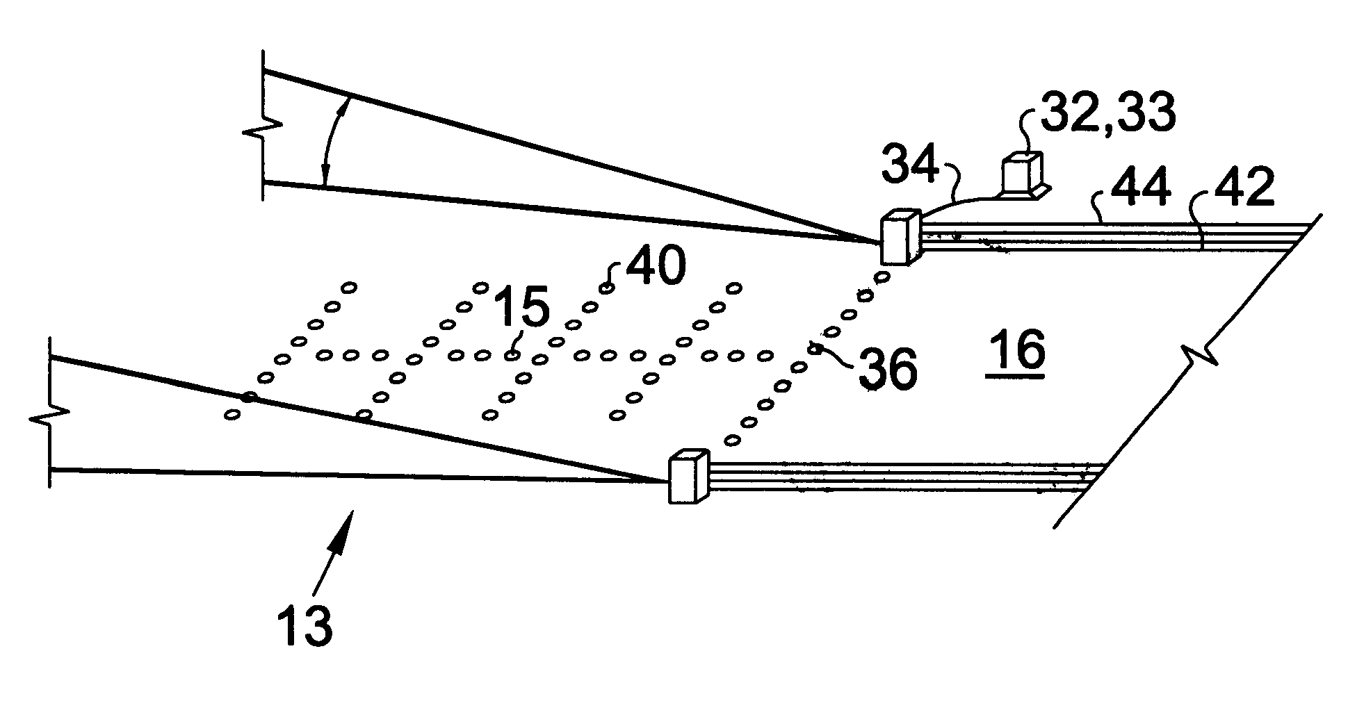
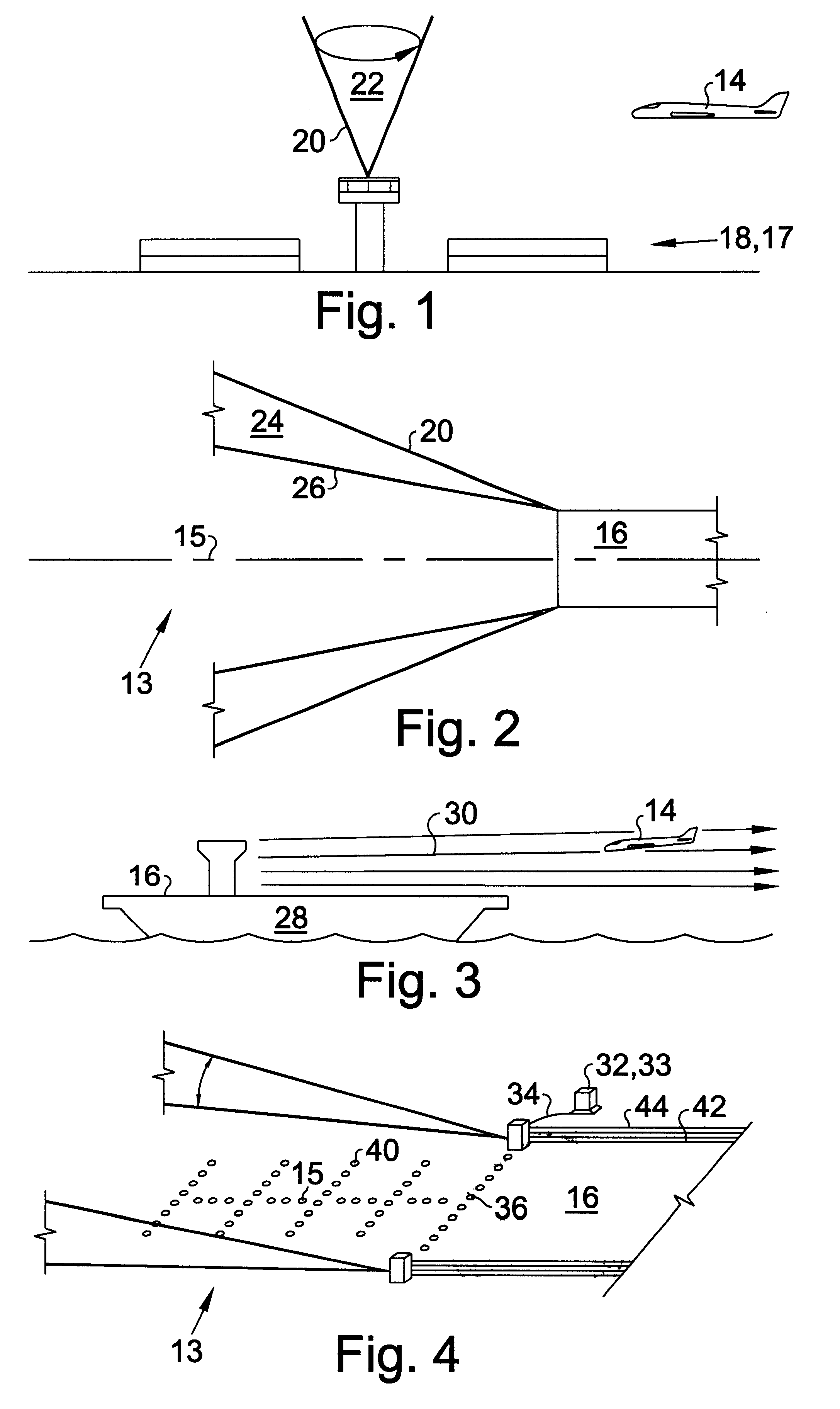
Turning now to the drawings and more particularly to FIG. 1 we have an elevational view of an airport 18 having an upwardly projected revolving laser beam 20 to identify the location of the airport 18. An aircraft landing location 17 is defined in this application to include either or both of an airport 18, or a runway 16. A method of illuminating an aircraft landing location 17 to facilitate identification and aircraft guidance thereto comprises the following step: projecting a laser beam 20 upwardly from the location 17 so that an aircraft 14 may be better able to target the landing location 17 particularly in conditions of poor visibility. To better attract attention, the laser beam 20 may circle so that its trajectory forms a cone 22. The laser beam 20 may also be colored to identify the particular landing location 17. This color might be one color selected from a color code which would identify the size and military or civilian nature of the airport 17. The Miami and Oploka air...


PUM


Abstract

FAA regulations mandate that a pilot must have sufficient visibility to see the airport, and then the runway before landing; and sufficient visibility to see a substantial portion of the runway before taking off. In adverse weather conditions when visibility is reduced flights are cancelled, delayed, and rerouted to land where visibility is adequate. Poor visibility is one of the major causes of air traffic fatalities. One aspect of this invention discloses a method of illuminating an aircraft landing location to facilitate identification and aircraft guidance thereto comprising the following steps: projecting a laser beam upwardly from the location so that an aircraft may be better able to target the landing location particularly in conditions of poor visibility. A preferred aspect of this invention provides for a method as above wherein the landing location comprises a runway and wherein the laser beam is projected upwardly from the runway and in a direction of the approach to the runway so that aircraft wanting to land can be guided to the runway. Most preferably the beam oscillates up and down so that generally a triangular wall of light is projected. With two beams, each projected from an opposite side of the runway and each projecting upwardly, towards the approach to the runway, and slightly away from a centerline of the runway side portions of a funnel indicating an approach to the runway may be projected.

Description

This invention relates to airport safety and the lighting of runways. More particularly this invention relates to a method of illuminating runways so that their visibility from the air remains adequate even in adverse weather conditions.FAA regulations mandate that a pilot, at set altitudes while descending to land, must have sufficient visibility to first see the airport, and then the runway. If at the predetermined altitudes the pilot is unable to either see the airport or the runway he is required to abort landing. When about one thousand feet from the runway, about one hundred feet up, and while travelling at about one hundred and eighty mph the pilot has about seven seconds to commit to landing.On January 26'th of this year eleven people were killed and 89 injured on American Airlines flight 1420. About 5 minutes before touchdown Captain Richard Buschman said he hated droning around without having some clue where he was. Heavy rain had reduced visibility to less than a mile. Ca...

Claims


Application Information

Patent Timeline
Patent Type & Authority Patents(United States)
IPC IPC(8): B64F1/20B64F1/00
CPCB64F1/20
Inventor REASON, RICHARD E.
Owner REASON RICHARD E
Learn More