Feedforward amplifier

a technology of amplifiers and amplifiers, applied in amplifiers, amplifier modifications to reduce noise influence, electrical devices, etc., can solve the problems of reducing the distortion of main amplifiers, reducing the power consumption of main amplifiers 6, and less production in band edges

Inactive Publication Date: 2001-12-04
PANASONIC CORP
View PDF4 Cites 63 Cited by
  • Summary
  • Abstract
  • Description
  • Claims
  • Application Information

AI Technical Summary

Problems solved by technology

Although distortion components produced in a region very close to the channel band can be sufficiently suppressed, therefore, there arises a problem in that those produced in a region of the band edge are more hardly suppressed.
The configuration of the conventional art has a second problem in that the power consumption of the main amplifier 6 is large.
This means that the main amplifier produces lower distortion, but is lower in power efficiency and consumes a large power.
When a class AB amplifier is used so as to enhance the efficiency, distortion is increased and higher order intermodulation is caused, so that distortion is produce

Method used


Image

  • Feedforward amplifier
  • Feedforward amplifier
  • Feedforward amplifier

Examples


Embodiment Construction

Hereinafter, the invention will be described with reference to the accompanying drawings showing its embodiments.

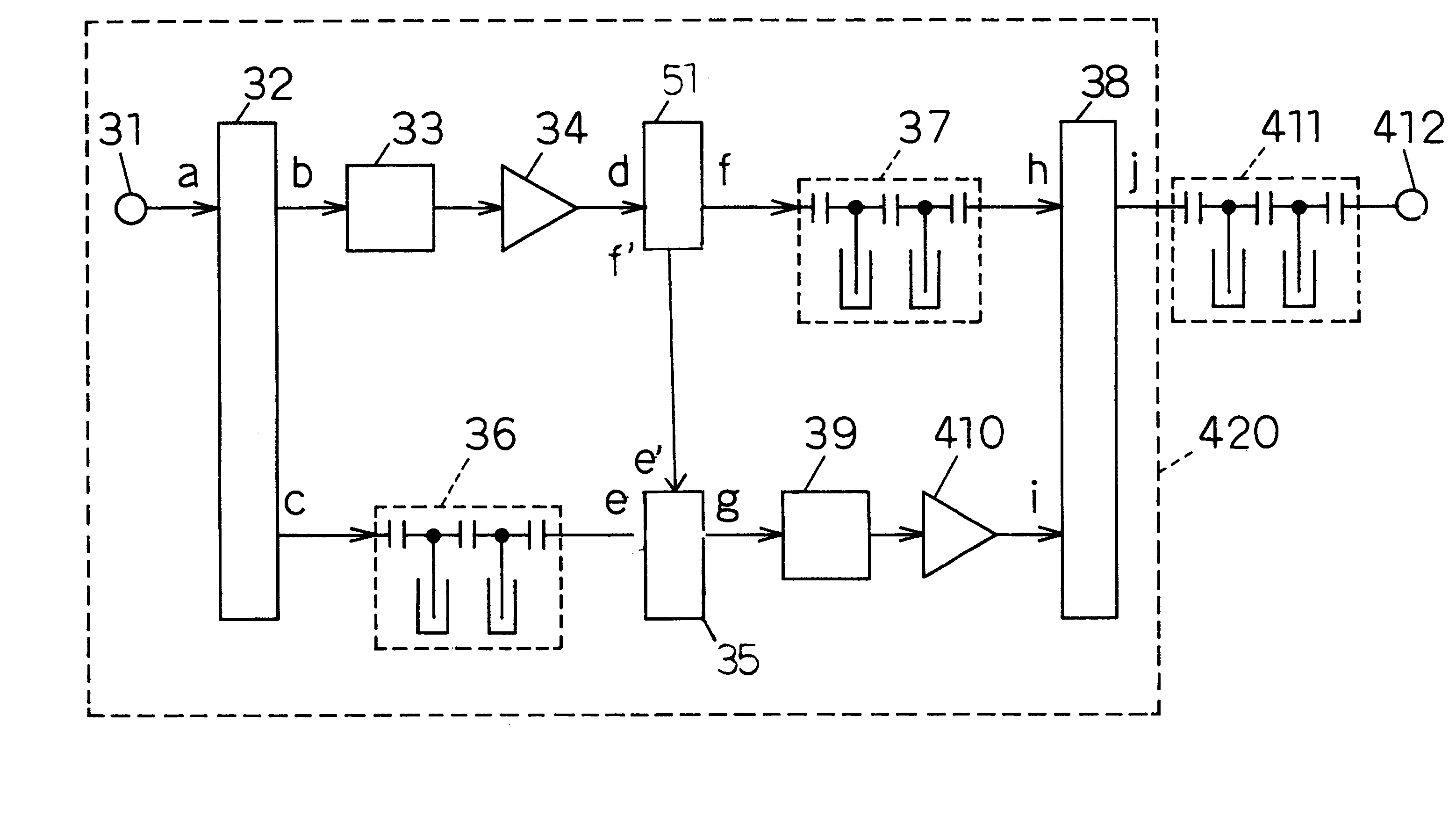
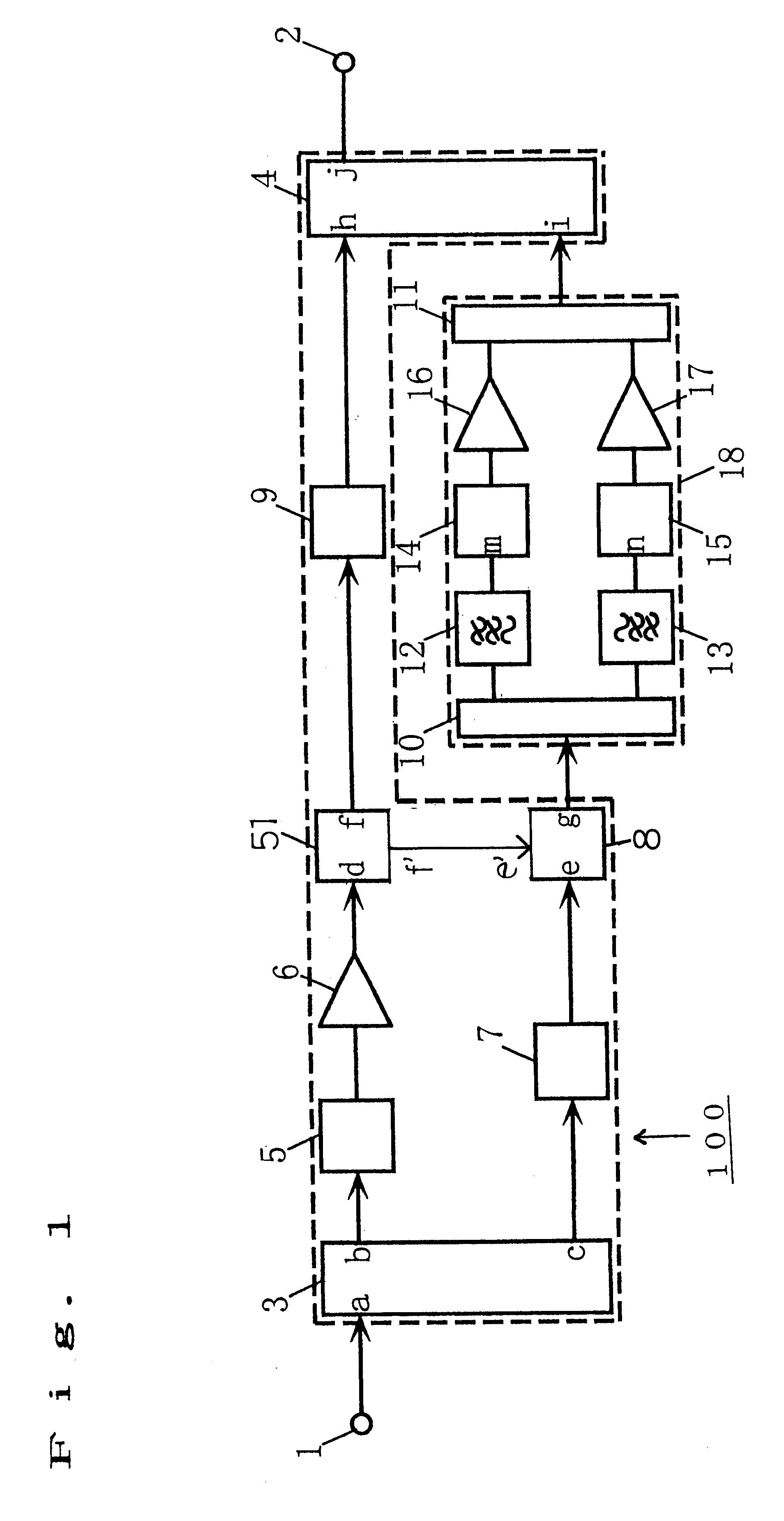
FIG. 1 is a diagram of a feedforward amplifier which is an embodiment according to the first and second aspects of the invention. As shown in the figure, in a feedforward amplifier 100, an input terminal 1 allows an external signal to be input to the feedforward amplifier 100. An output terminal 2 allows a signal to be output from the feedforward amplifier 100 to the external. A power divider 3 divides the input from the input terminal 1 into two signals, and supplies the signals to a vector adjuster 5 and a delay circuit 7, respectively. A main amplifier 6 amplifies an input from the vector adjuster 5. A directional coupler 51 is such means for receiving signal from the main amplifier 6 and ouputting almost signals to delay circuit 7 from the main port and outputting a few signals to the after-mentioned power combiner 8. A power combiner 8 receives inputs from the couple...


PUM


Abstract

A feedforward amplifier includes a power divider for dividing the input signal into first and second signals. The first signal is processed in a first path that includes, in sequence, a first vector adjuster, a main amplifier, a directional coupler and a delay circuit. The second signal is delayed in a second path that includes, in sequence, another delay circuit, a first power combiner and an auxiliary amplifier block. The first power combiner combines the first signal, by way of a coupling port from the directional coupler, with the second signal to provide a combined signal into the auxiliary amplifier block. The auxiliary amplifier block further divides the second signal into two divided signals, each having a respective non-overlapping frequency band. The two divided signals are respectively vector adjusted, amplified, and then recombined. The recombined signal is then recombined with the processed signal in the first path to provide the desired output signal.

Description

1. Field of the InventionThe present invention relates to a feedforward amplifier which is mainly used in a device of a base station of a mobile communication system.2. Related Art of the InventionIn order to collectively amplify a large number of signal channels, recently, a device of a base station of a mobile communication system is requested to be provided with a power amplifier which is excellent both in efficiency and linearity. The linearity is realized by performing distortion compensation according to the feedforward system.A feedforward amplifier is described by, for example, John L. B. Walker, "High-Power GaAs FET Amplifiers," Artech House, 1993, p.p. 332 to 333.FIG. 7 is a diagram showing an example of the configuration of a feedforward amplifier of the conventional art. As shown in the figure, in a feedforward amplifier 600, an input terminal 1 allows an external signal to be input to the feedforward amplifier 600. An output terminal 2 allows a signal to be output from ...

Claims


Application Information

Patent Timeline
IPC IPC(8): H03F1/32
CPCH03F1/3229
Inventor MIYAJI, MASAYUKIISHIDA, KAORUKOSUGI, HIROAKIKUGOU, SHIN'ICHI
Owner PANASONIC CORP
Why Eureka
Try Eureka