Donor rolls and methods of making donor rolls

a technology of donor rolls and donor rolls, applied in the field of donor rolls, can solve the problems of runout, change the size of the development zone along the way, and runout can still occur

Inactive Publication Date: 2001-12-04
XEROX CORP
View PDF21 Cites 26 Cited by
  • Summary
  • Abstract
  • Description
  • Claims
  • Application Information

AI Technical Summary

Problems solved by technology

Also, if the donor roll is mounted so that it rotates about an axis that does not coincide with its true geometrical axis, runout can occur.
Likewise, if the donor roll dimensions are not sufficiently uniform and the donor roll and / or journals are rounded, runout can still occur even if the donor roll is properly mounted to rotate about its true geometrical axis.
If the donor roll has excessive runout, it can change the size of the development zone along the length of the donor roll by the amount of the runout.
If the development zone of the development apparatus changes excessively during imaging due to poor dimensional control of the components, then the ability of the apparatus to effectively and controllably donate charged toner particles to the photoconductive member and achieve high-quality image development can be adversely affected.
Particularly, if the total allowable deviations or the development zone nonuniformity of the components involved in the transfer of the charged toner particles from the donor roll to the photoconductive member is too high such that gap non-uniformity occurs then toner may conceivably not deposit uniformly.

Method used


Image

  • Donor rolls and methods of making donor rolls
  • Donor rolls and methods of making donor rolls
  • Donor rolls and methods of making donor rolls

Examples


Embodiment Construction

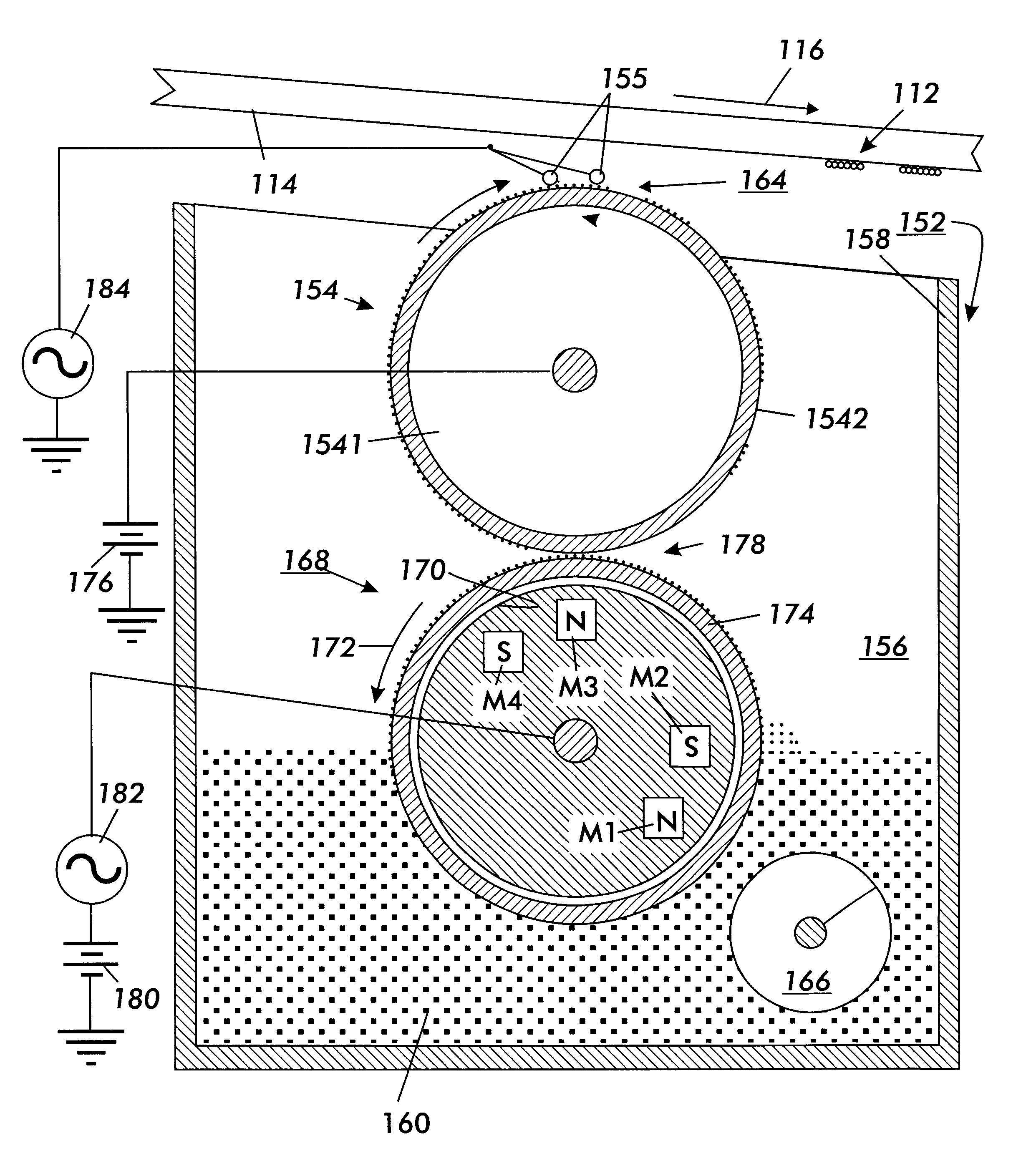
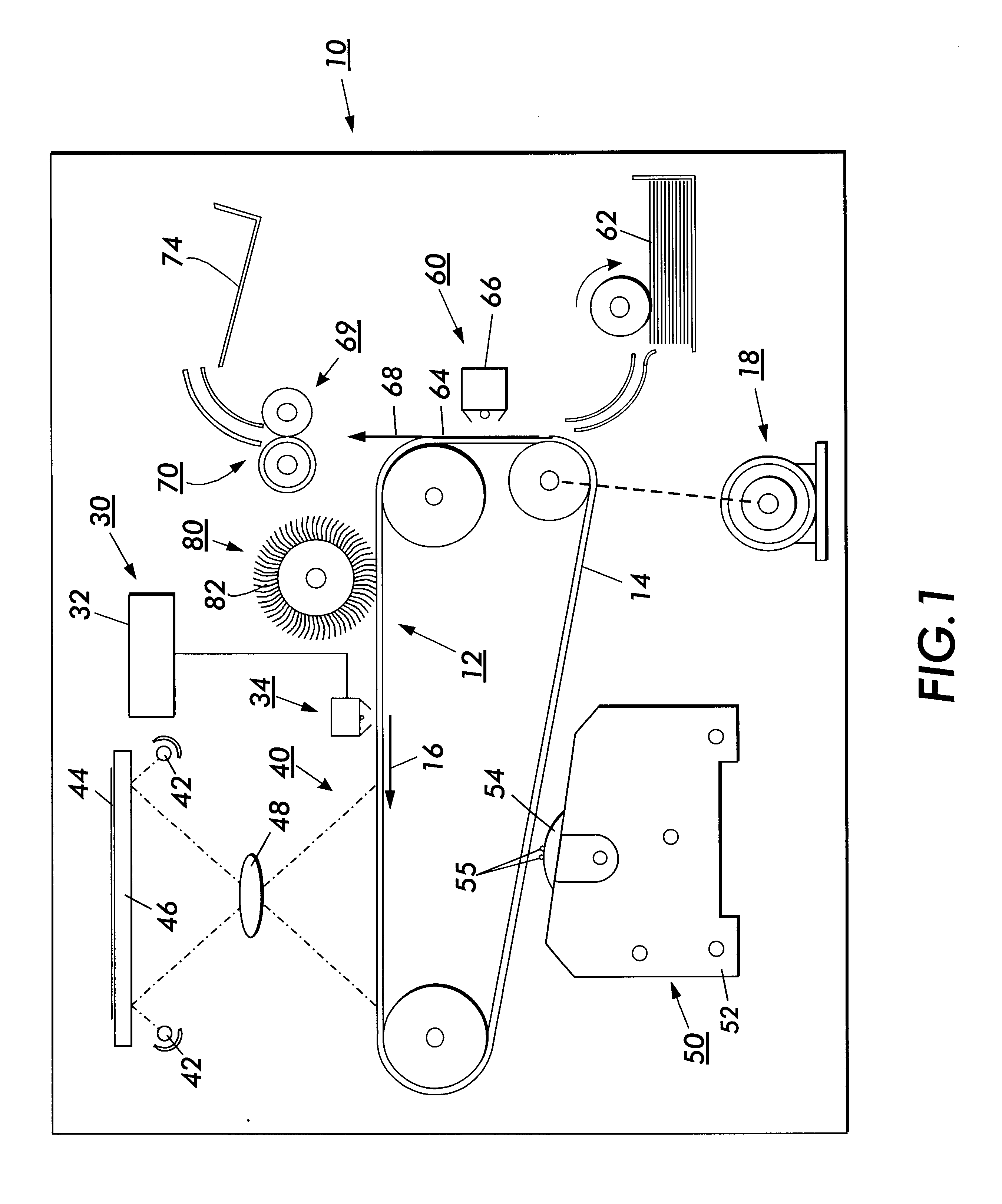
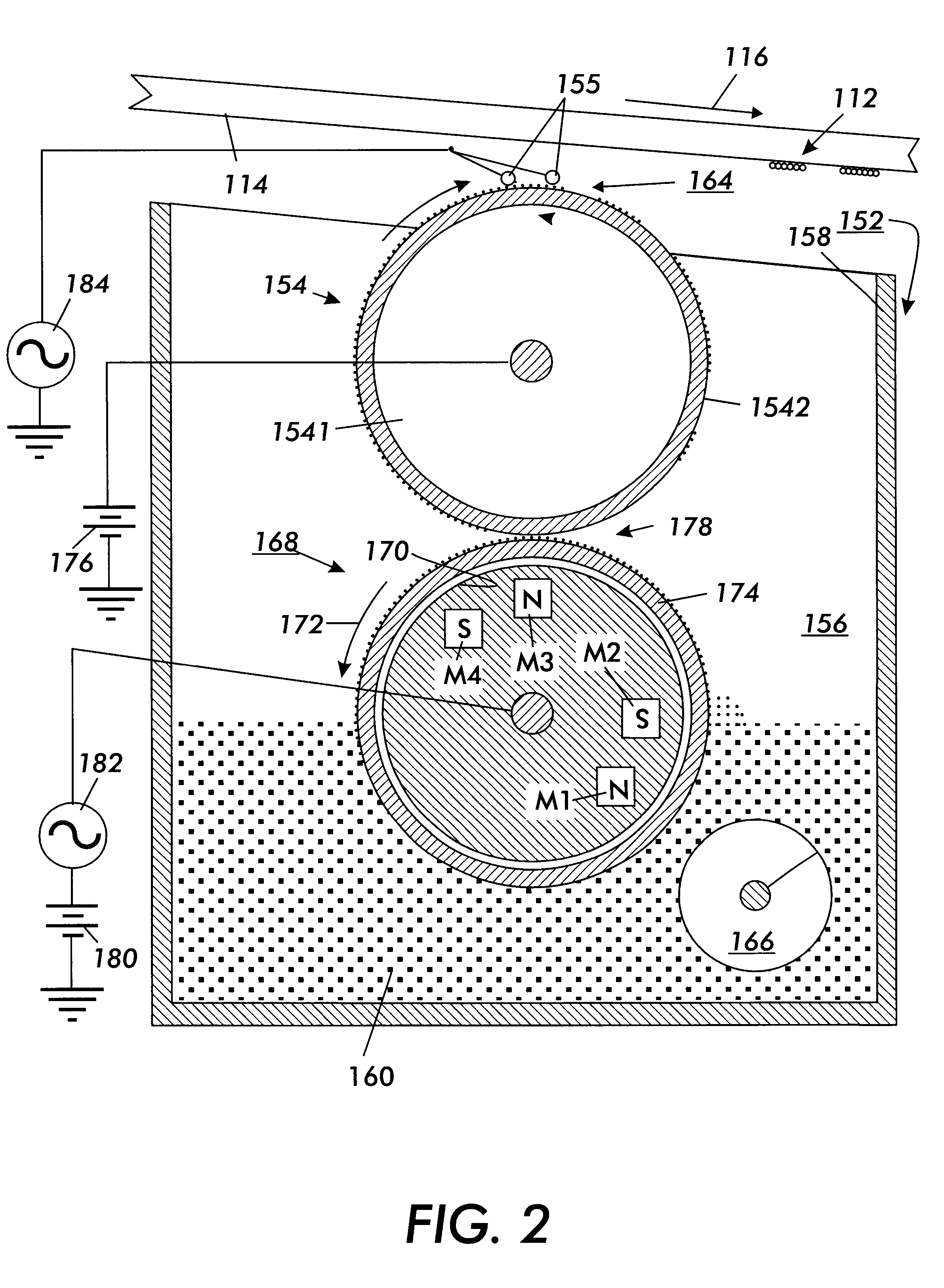
FIG. 1 shows a scavengeless electrostatic imaging apparatus 10 including an exemplary embodiment of a donor roll 54 according to this invention. The imaging apparatus 10 includes an image bearing member in the form of a belt 12 having an outer photoconductive surface 14. The image bearing member can alternatively comprise other types of photoconductive image bearing members, such as a drum having a photoconductive surface. The belt 12 moves in the direction of the arrow 16 to advance successive portions of the photoconductive surface 14 sequentially through various processing stations during the imaging process. The belt 12 is driven by a motor 18.

Initially, a portion of the belt 12 passes through a charging station 30 where a power supply 32 causes a corona generating device 34 to charge a portion of the photoconductive surface 14 of the belt 12.

The charged portion of the belt 12 is advanced to a exposure station 40. At the exposure station 40, one or more light sources such as lam...


PUM

PropertyMeasurementUnit
outer diameteraaaaaaaaaa
arithmetical mean roughnessaaaaaaaaaa

Abstract

A roller includes a core and a ceramic coating formed over the core. The roller has a composite runout of less than 20 mum and a total indicator reading runout of less than 7 mum. The ceramic coating has a smooth finish and has controlled electric properties. This roller can be used as a donor roller for transporting toner to a photoconductive member so as to achieve high-quality image development.

Description

1. Field of InventionThis invention relates to electrostatographic imaging devices.2. Description of Related ArtElectrostatic reproduction and printing involves uniformly charging a photoconductive member, or photoreceptor, and imagewise discharging it, or imagewise exposing it, based on light reflected from, or otherwise representing, an original image being reproduced or printed. The result is an electrostatically-formed latent image on the photoconductive member. The latent image is developed by bringing a charged developer material into contact with the photoconductive member to form a toner powder image. The toner powder image is transferred to a receiving sheet and then fused by heating.This process can be modified to form color images. One type of process, called image-on-image processing, superimposes toner powder images of different color toners onto the toner prior to the transfer of the composite toner powder image onto the substrate.Two-component and single-component dev...

Claims


Application Information

Patent Timeline
Patent Type & Authority Patents(United States)
IPC IPC(8): G03G15/08
CPCG03G15/0818G03G2215/0621G03G2215/0643G03G2215/0863
Inventor JASKOWIAK, TIMOTHY R.KAZAKOS, ANN M.LONGHENRY, JOY L.SCHLAFER, MICHELLE L.MULROY, GRETHEL K.DIGRAVIO, THOMAS L.TAFT, KEVIN H.WHITE, FREDERICK B.GELIN, MARK
Owner XEROX CORP
Why Eureka
Try Eureka