Fluid drop projecting head using taper-shaped chamber for generating a converging surface wave

a projecting head and converging surface technology, applied in printing and other directions, can solve the problems of difficult to form so fine fluid drops, less reliable, nozzles are more susceptible to choking and consequently less reliable, etc., and achieve the effect of varying the drop siz

Inactive Publication Date: 2001-12-11
NEC CORP
View PDF31 Cites 46 Cited by
  • Summary
  • Abstract
  • Description
  • Claims
  • Application Information

AI Technical Summary

Benefits of technology

is to provide a fluid drop projecting app...

Problems solved by technology

However, with any of the above-described fluid drop projecting apparatuses, it is difficult to form so fine fluid drops for the following reasons.
However, such a small nozzle bore would make the nozzle more susceptible to choking and accordingly less reliable.
Therefore, it is extremely difficult to form fluid drops as fine as a few .mu.m to 20 .mu.m in diameter.
Moreover, the smaller nozzle bore means the need for more precise machining with the consequence that, where minute fluid drops have to be projected from an apparatus based on the principle of pumping, a problem arises not only with reliability but also with productivity.
This entails a problem in drop-by-drop controllability, which has to be precise for ink jet recording heads or bump forming devices.
In other words, it is difficult to precisely control the positions and volumes of fluid drops reaching at the recording medium.
The utili...

Method used


Image

  • Fluid drop projecting head using taper-shaped chamber for generating a converging surface wave
  • Fluid drop projecting head using taper-shaped chamber for generating a converging surface wave
  • Fluid drop projecting head using taper-shaped chamber for generating a converging surface wave

Examples


embodiment 1

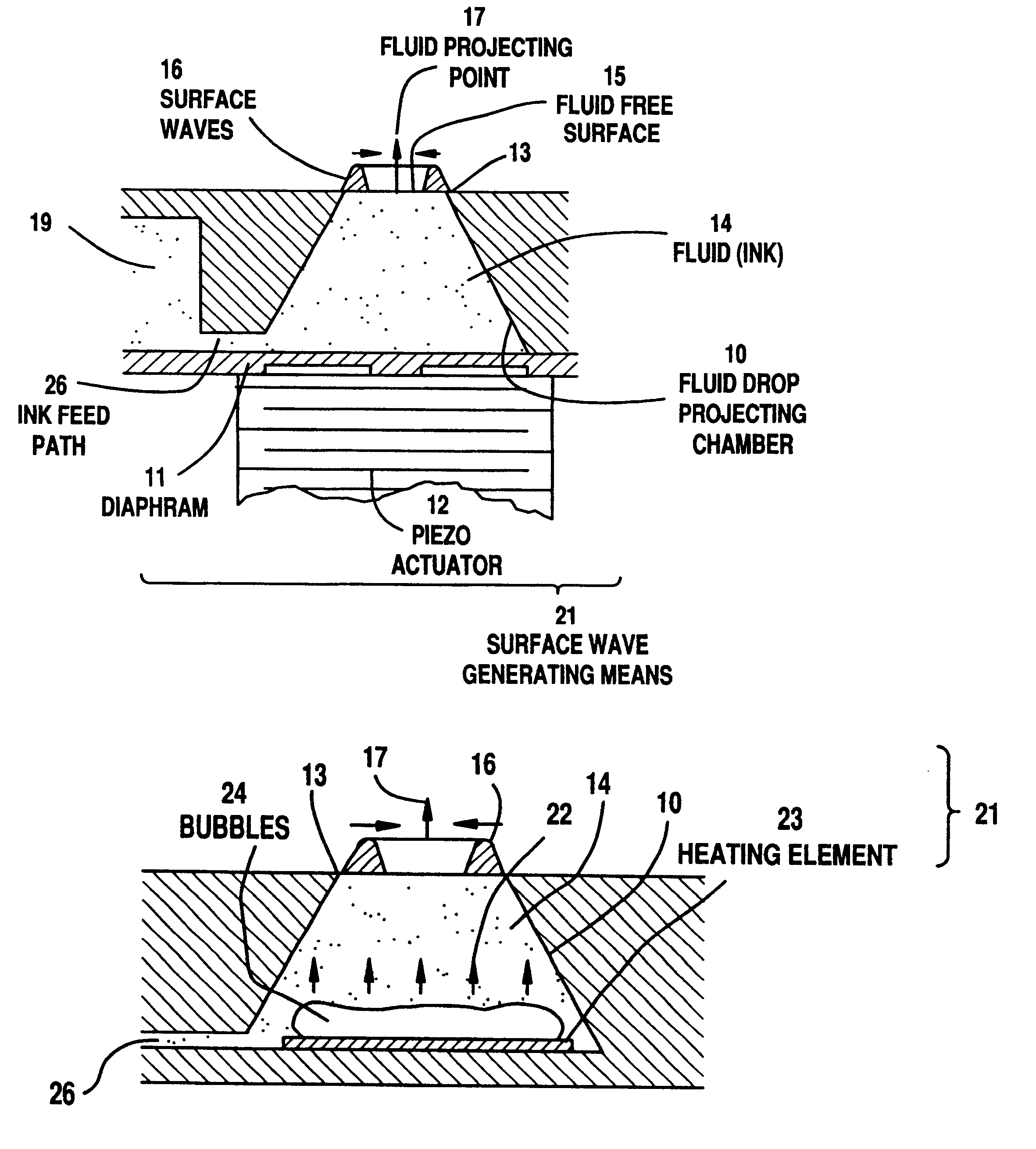
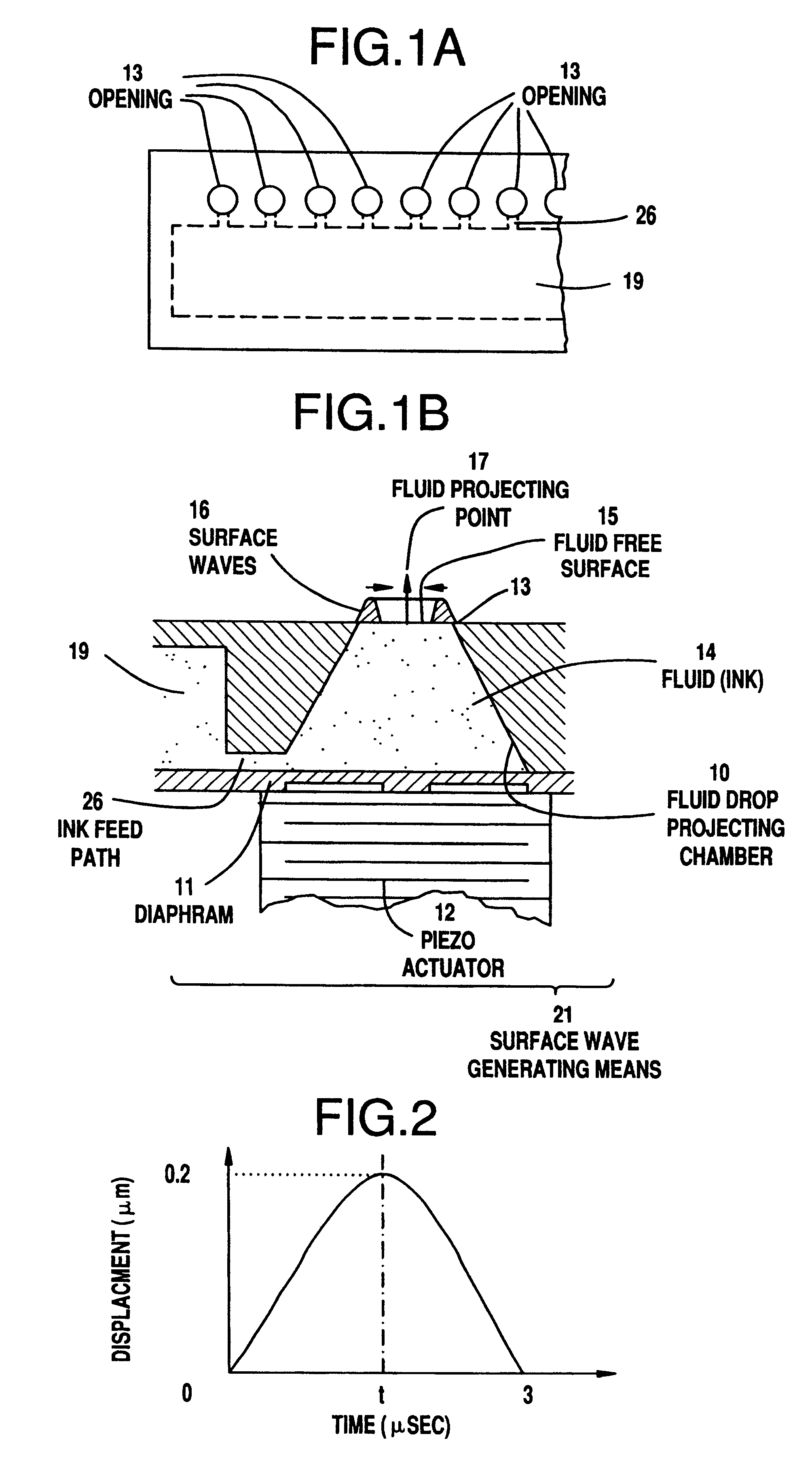
FIGS. 1A and 1B respectively show a plan and a cross section of fluid drop projecting apparatuses, which constitute a first preferred embodiment of the invention. As illustrated in FIG. 1A, Embodiment 1 comprises a plurality of fluid drop projecting apparatuses arranged in parallel for application to an ink jet recording head. Each individual fluid drop projecting apparatus, as illustrated in FIG. 1B, comprises a fluid drop projecting chamber 10 whose opening bore gradually expands in the direction of depth, a diaphragm 11 connected to the bottom of the fluid drop projecting chamber 10, and a pizeo actuator 12 connected to the diaphragm 11. The fluid drop projecting chamber 10 is filled with fluid ink 14, and is in continuity to an ink tank 19 via an ink feed path 26. Here, an opening 13 and the bottom of the fluid drop projecting chamber 10 are circularly shaped, respectively measuring 80 .mu.m and 240 .mu.m in diameter, and the fluid drop projecting chamber 10 is 100 .mu.m deep. T...

embodiments 2 and 3

FIGS. 6A and 6B show plans of fluid projecting apparatuses which constitute respectively second and third preferred embodiments of the present invention. FIG. 6A shows a plan of fluid drop projecting apparatuses each having an opening 13 of a regular dodecagon circumscribing a circle of 80 .mu.m in diameter, and FIG. 6B, a plan of fluid drop projecting apparatuses each having an opening 13 of a regular hexagon circumscribing a circle of 80 .mu.m in diameter. Other aspects than the shape of the opening 13 of these embodiments were the same as those of the fluid drop projecting apparatus illustrated in FIG. 1B. Under the same driving conditions for the piezo actuator 12 as for that of Embodiment 1, no fluid drop was projected by either of the apparatuses shown in FIGS. 6A and 6B. This state was observed stroboscopically in the same manner as for Embodiment 1. As in Embodiment 1, it was witnessed that the driving of the actuator resulted in the formation of surface waves in conformity ...

embodiment 4

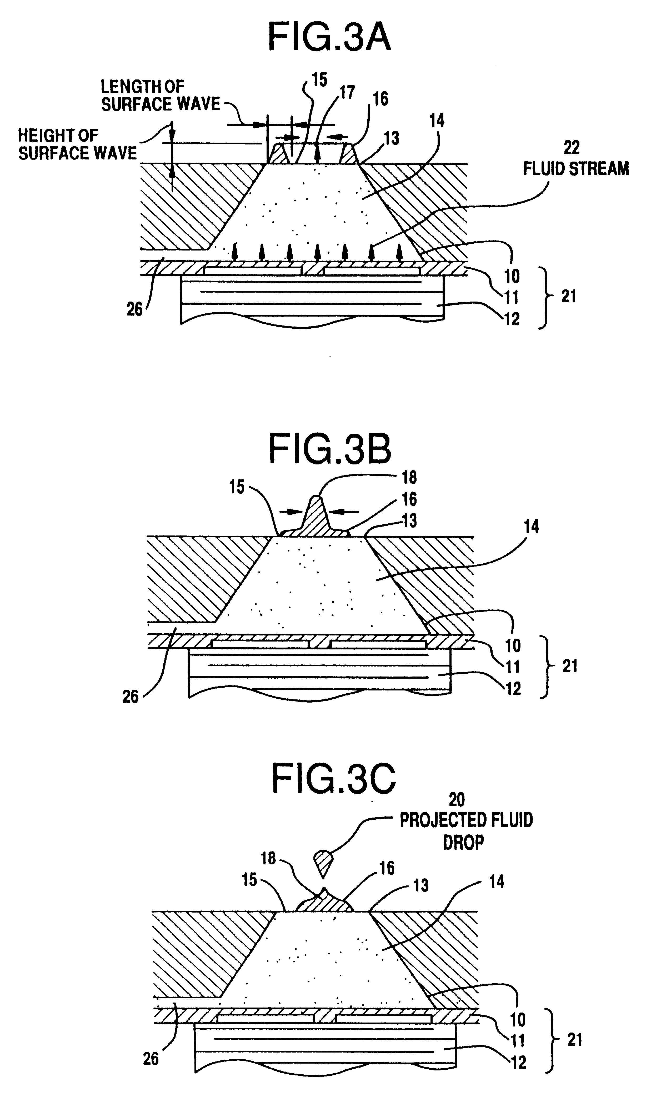
In Embodiment 4, the bore of the circular opening 13 is 1 mm, greater than in Embodiment 1. Except for the opening 13, this embodiment has the same configuration as Embodiment 1 illustrated in FIG. 1B. When the piezo actuator 12 was driven for t=200 .mu.sec and its displacement d was gradually increased, steady projection of fluid drops became possible at d=4.8 .mu.m, when the drop diameter was about 280 .mu.m. It was confirmed that, even when the opening bore was a full millimeter, fluid drops 20 far smaller than the bore of the opening 13 could be projected.

Next, an experiment was carried out to determine the dependence of the diameter of projected fluid drops on the drive waveform of the piezo actuator 12. While the piezo actuator 12 was driven for t=200 .mu.sec in the foregoing example in which fluid drops of 280 .mu.m were projected, fluid drop projection was further attempted with different drive durations, varied to 145, 100 and 60 .mu.sec. The displacement d of the piezo act...


PUM


Abstract

A fluid drop projecting apparatus which can fly, one by one, fluid drops far smaller than the opening bore from which the drops are projected, and moreover cay readily vary the size of the fluid drops, is provided. To this end, surface waves travelling toward a fluid drop projecting point are applied on the free surface of fluid in a fluid drop projecting chamber having an opening. The surface waves are generated by a surface wave generator including the fluid drop projecting chamber, a diaphragm and a piezo actuator. As the surface waves are generated by the surface wave generator at substantially equal distances from a fluid drop projecting point, the height of the surface waves gradually increases, amplified by their interference, and fluid drops are separated at and projected from the fluid drop projecting point.

Description

The present invention relates to an apparatus for projecting fluid drops, and more particularly to an ink jet recording head for causing minute fluid drops to fly to a recording medium to record visual images. The invention relates to an apparatus for projecting fluid drops, and more particularly to an apparatus for causing electroconductive materials, which are solid at normal temperature and melted by heating, in a state of fluid drops to a circuit substrate or the like and forming bumps thereon for connection to LSIs or the like.DESCRIPTION OF THE PRIOR ARTFluid drop projecting apparatuses according to the prior art for use in ink jet printers among others include one disclosed in the U.S. Pat. No. 3,946,398 in which, as illustrated in FIG. 13A, a piezo element 12 is oscillated to expand the volume of an ink chamber 30 thereby to suck a fluid 14, such as ink, from an ink tank (not shown) and, afterwards, as illustrated in FIG. 13B, the volume of the ink chamber 30 is compressed t...

Claims


Application Information

Patent Timeline
IPC IPC(8): B41J2/14B41J2/04B41J2/015B41J2/045B41J2/05B41J2/055
CPCB41J2/1404B41J2/14274B41J2002/14322B41J2002/14387
Inventor KOJIMA, RYUICHIOTSUKA, YASUHIROTAKIZAWA, FUMINORI
Owner NEC CORP
Why Eureka
Try Eureka