

Automatic frequency control in FSK receiver using voltage window deviation
a frequency control and automatic technology, applied in the field of fsk receivers, can solve the problems of deteriorating receiving status conditions, integrators or averaging circuits that require an integration or averaging time longer than the data rate, and short sync signals
- Summary
- Abstract
- Description
- Claims
- Application Information
AI Technical Summary
Problems solved by technology
Method used
Image

Examples
first embodiment
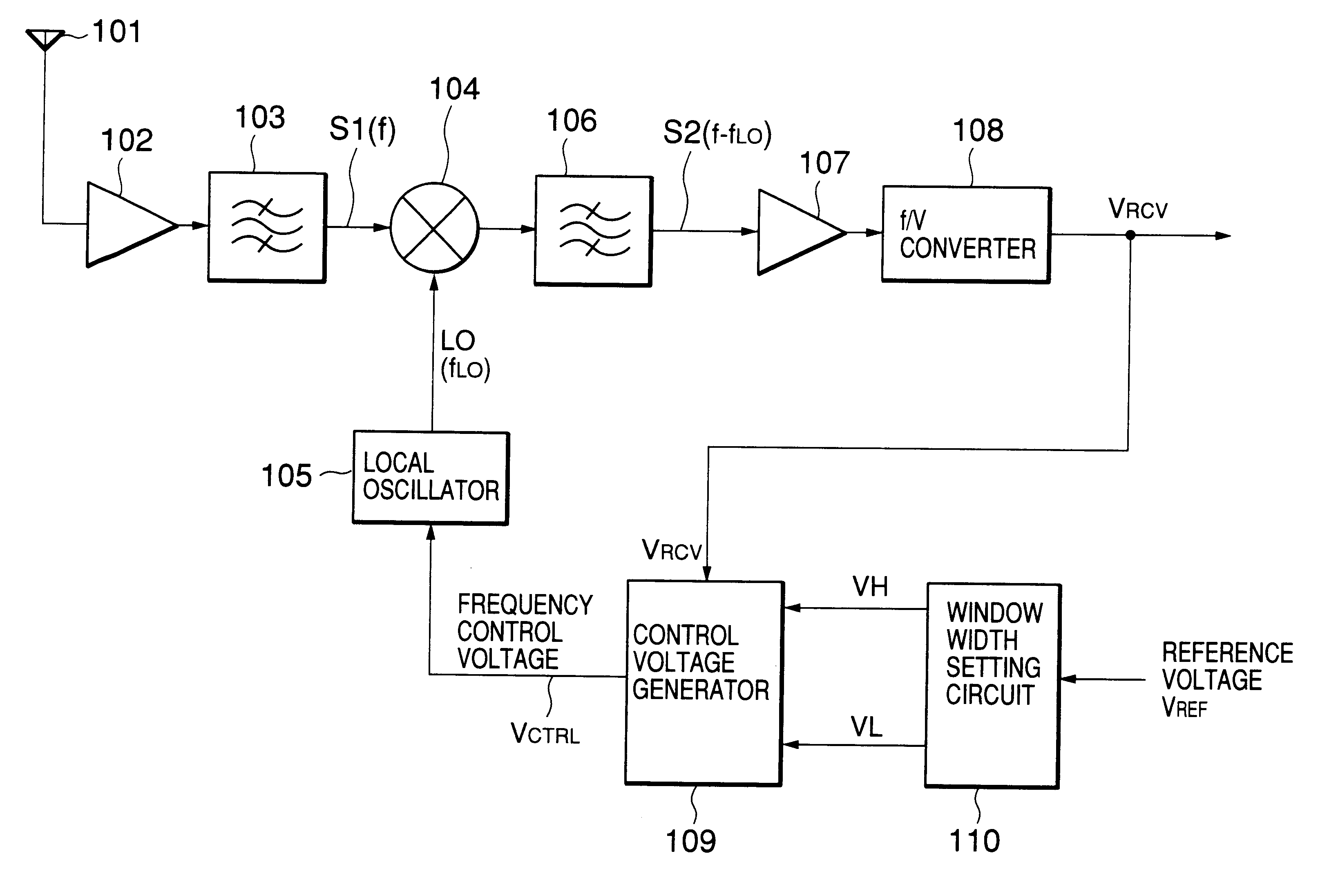
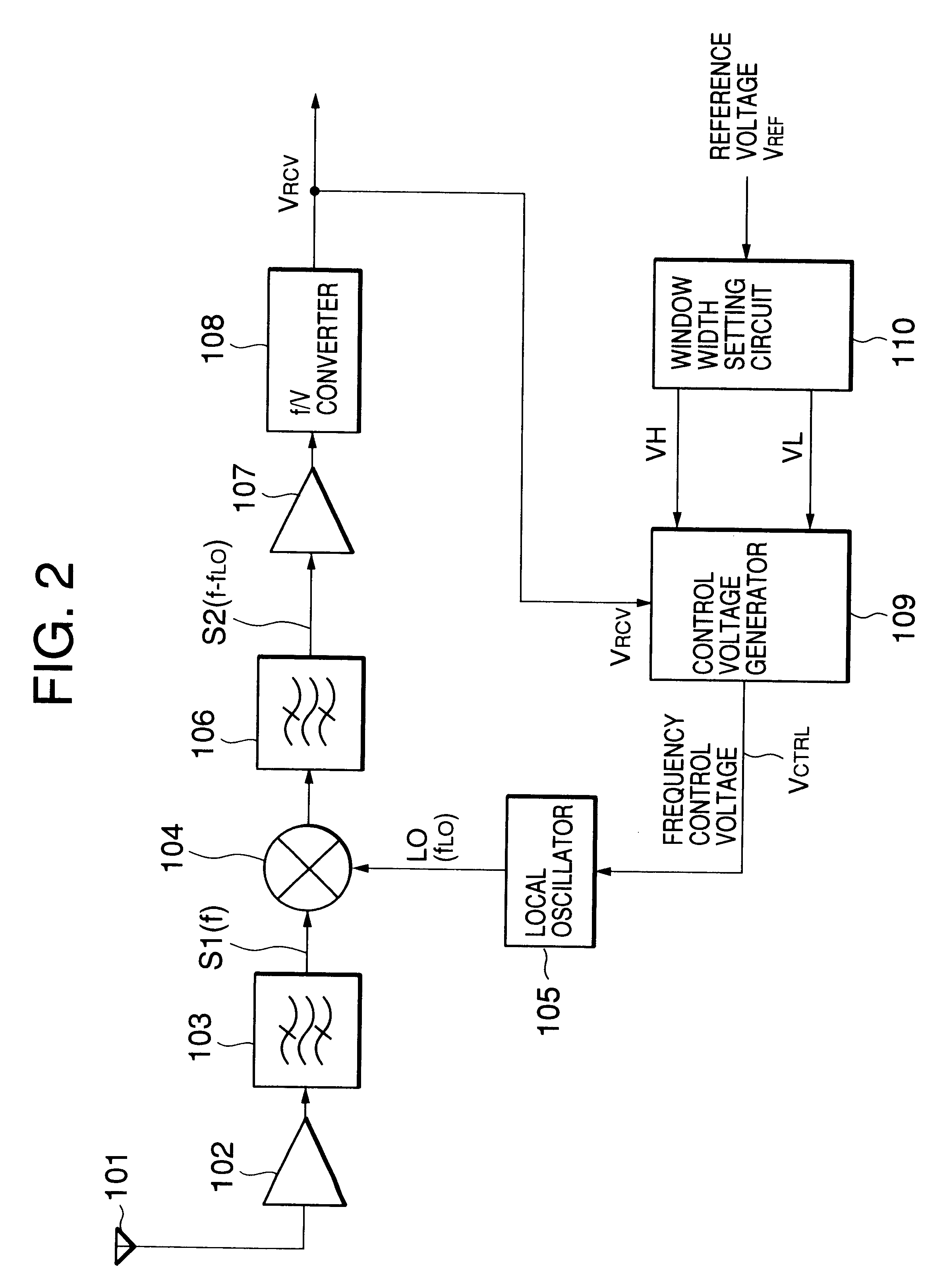
Then, operations of the FSK receiver shown in FIG. 2 and the first embodiment shown in FIG. 6 will be described referring to FIG. 8.
A radio-frequency FSK signal is received by the antenna 101, amplified by the high-frequency amplifier 102, and input to the mixer 104 through the band-pass filter 103. The mixer 104 mixes the output signal S1 of the band-pass filter 103 with the local-oscillation signal LO of the local oscillator 105. The frequency-converted FSK signal is passed through the band-pass filter 106 to produce the second FSK signal S2 having an intermediate frequency of (f-f.sub.LO).
After the output signal (f-f.sub.LO) of the band-pass filter 106 is input to the limiter amplifier 107 where it is limited for amplitude, an output signal of the limiter amplifier 107 is input to the f / V convertor 108.
The output voltage V.sub.RCV of the f / V converter 108 is input to the control voltage generator 109. The window width shown in FIG. 8 set by the window-width setting circuit 110, t...
second embodiment
Then, the second embodiment of the present invention is described below by referring to the accompanying drawings. FIG. 9 is a circuit diagram showing the structure of the second embodiment.
Referring to FIG. 9, the structure of the window-width setting circuit 110 is the same as that in FIG. 6. Although the description of the window-width setting circuit 110 is omitted, the structure of the control voltage generator 109 is different from that in FIG. 6. That is, in the case of the control voltage generator 109 in FIG. 9, constant-current sources 24 and 25 are newly added and comparators 21 and 22 are used instead of the VI amplifiers 18 and 19.
The inverting input terminal of the comparator 21 is connected to the connection point between the constant-current source 13 and the resistor 14 of the window-width setting circuit 110. The non-inverting input terminal of the comparator 22 is connected to the connection point between the resistor 15 and the constant-current source 16 of the w...
third embodiment
Referring to FIG. 12, the third embodiment is different from the second embodiment of FIG. 9 in that four reference voltages are output from the window-width setting circuit 110. That is, the window-width setting circuit 110 is constituted by a series circuit including a constant-current source 13, resistors 26 to 29, and a constant-current source 16 which are connected in series between the power supply line 12 and the GND line. The reference voltage V.sub.REF is applied to the connection point between the resistors 27 and 28.
In the window-width setting circuit 110, a first upper-limit voltage VH1 is generated on the connection point between the resistors 26 and 27. A second upper-limit voltage VH2 (VH2>VH1) is generated on the connection point between the constant-current source 13 and the resistor 26 as shown in FIG. 13. A first lower-limit voltage VL1 is generated on the connection point between the resistors 28 and 29 and the second lower-limit voltage VL2 (VL2<VL1) is generate...
PUM
 Abstract
Description
Claims
Application Information