Device for measuring pressure points to be applied by a compressive orthotic device

a compression orthotic device and pressure point technology, applied in the direction of electrical/magnetic measuring arrangements, using electrical/magnetic means, medical science, etc., can solve the problems of falsification of measurement, poor accuracy, and difficulty in ensuring the reproducibility of methods

Inactive Publication Date: 2002-01-01
INNOTHERA TOPIC INT
View PDF9 Cites 209 Cited by
  • Summary
  • Abstract
  • Description
  • Claims
  • Application Information

AI Technical Summary

Problems solved by technology

Nevertheless, that method suffers from three major drawbacks:
firstly, its accuracy is poor given that firstly the pressure applied by the stocking is relatively small compared with the sensitivity of the pressure gauge capsule, and secondly because placing the sensor between the stocking and the tree changes the tension of the stocking specifically at

Method used


Image

  • Device for measuring pressure points to be applied by a compressive orthotic device
  • Device for measuring pressure points to be applied by a compressive orthotic device
  • Device for measuring pressure points to be applied by a compressive orthotic device

Examples


Embodiment Construction

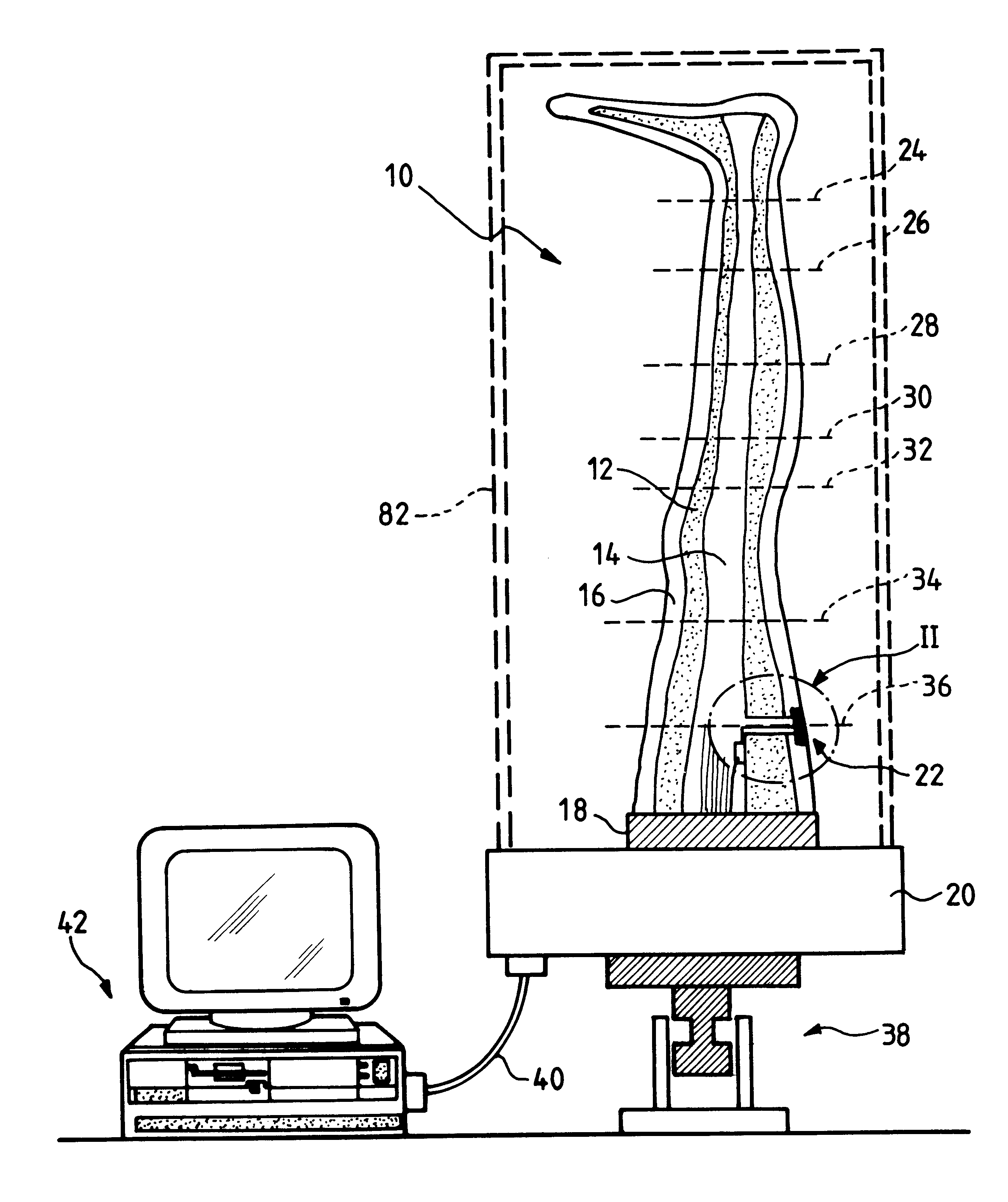
In FIG. 1, reference 10 designates overall a rigid former that is representative of a limb (or more generally of a portion of the body) on which compression is to be applied. In the example shown, it is constituted by a leg former having dimensions corresponding to one of the four sizes 1 to 4 of the standardized "Hohenstein model".

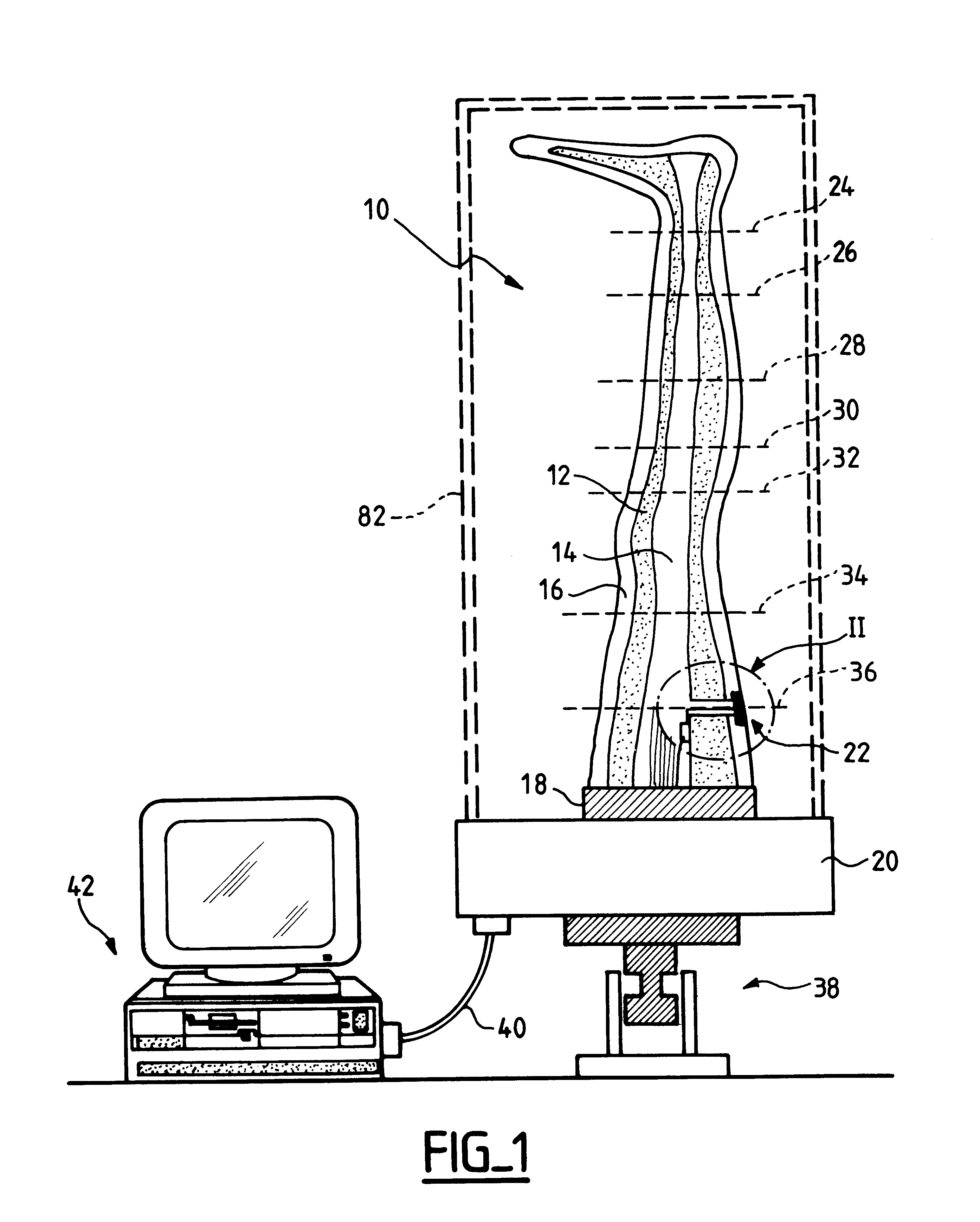
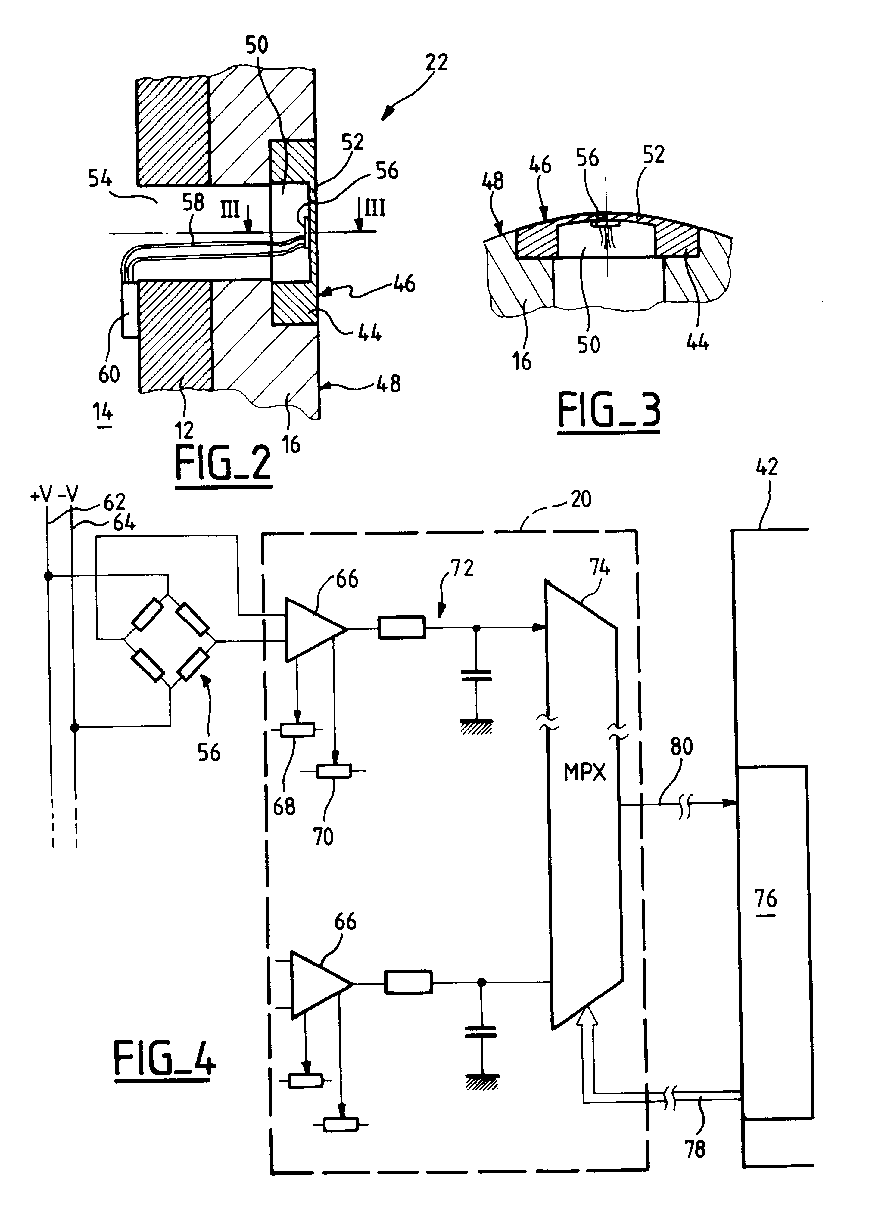
The former 10 has a central core 12 or "salmon" made of metal having a hollow center so as to provide an access tunnel 14 serving specifically to pass and keep together the wires connected to the various sensors (see below). The metal "salmon" 12 is covered in a covering 16, e.g. of epoxy resin, that is molded to have the same dimensions as the standardized jig or tree. The surface state of the covering 16 is made to be smooth and without roughnesses so as to make it easy to put an elastic stocking into place in uniform manner on the former 10.

Advantageously, e.g. to make it possible to exchange a faulty sensor or to verify the interconnections, the forme...


PUM


Abstract

The device comprises a rigid former reproducing the volume of a portion of the body and suitable for receiving the compressive orthosis. The former (10) incorporates a plurality of sensors (22) distributed over various points of the former and configured in such a manner as to avoid significantly modifying the surface profile of the former, the sensors essentially measuring the pressure applied locally on the former by the orthosis at the location of the sensor and perpendicularly to the surface of the former. Advantageously, at the location of the measurement point, each sensor comprises a thin wall capable of being subjected to microdeformation under the effect of the pressure applied by the orthosis, and means such as a strain gauge bridge, for example. The thin wall can constitute a portion of a support pellet which is fitted to the former in such a manner that its outside surface, which includes the thin wall, is flush with the outside surface of the former.

Description

1. Field of the InventionThe invention relates to measuring the restraining pressures that a compressive orthosis serves to apply on a portion of the body.2. Discussion of Prior ArtThe invention is more particularly described for the case where the portion of the body in question is the leg and the compressive orthosis is an elastic stocking. Nevertheless, the invention is not limited to that particular case and it applies to other types of orthosis and / or to other portions of the body, for example elastic strips for application to the leg or to a portion of the leg, a belt for applying pressure to the abdomen, etc.The pressures exerted by such orthoses are small, of the order of 0 to 100 hPa, and typically of the order of 20 hPa to 70 hPa, in relative pressure terms.Numerous factors can influence the value of this pressure and can give rise to differences from a standard nominal value, e.g. knitting machine adjustments, manufacturing tolerances, processing such as dying the stockin...

Claims


Application Information

Patent Timeline
IPC IPC(8): A61F13/08A61F13/06A61F5/01G01L5/00G01L7/00
CPCA61F13/08A61F5/01
Inventor TESTUD, JEAN-LOUISSENNOUNE, MOHAMMEDPRUDHOMME, JEAN-PIERREOUCHENE, AMINA
Owner INNOTHERA TOPIC INT
Why Eureka
Try Eureka