Electrostatic force detector with cantilever and shield for an electrostatic force microscope

a detector and electrostatic force technology, applied in the field of electrostatic force microscopes, can solve the problems of generating measurement errors, no further discussion, and low spatial resolution of currently available apparatuses

Inactive Publication Date: 2002-01-08
TREK BICYCLE CORPORATION
View PDF2 Cites 18 Cited by
  • Summary
  • Abstract
  • Description
  • Claims
  • Application Information

AI Technical Summary

Problems solved by technology

While on the one hand it is required to make a precise measurement of charge distribution on a photoreceptor drum, on the other hand the spatial resolution of currently available apparatus is fairly low.
Studies have been made relating to the scanning electrostatic force microscope, however, the theoretical aspects of those studies were only extended

Method used


Image

  • Electrostatic force detector with cantilever and shield for an electrostatic force microscope
  • Electrostatic force detector with cantilever and shield for an electrostatic force microscope
  • Electrostatic force detector with cantilever and shield for an electrostatic force microscope

Examples


Embodiment Construction

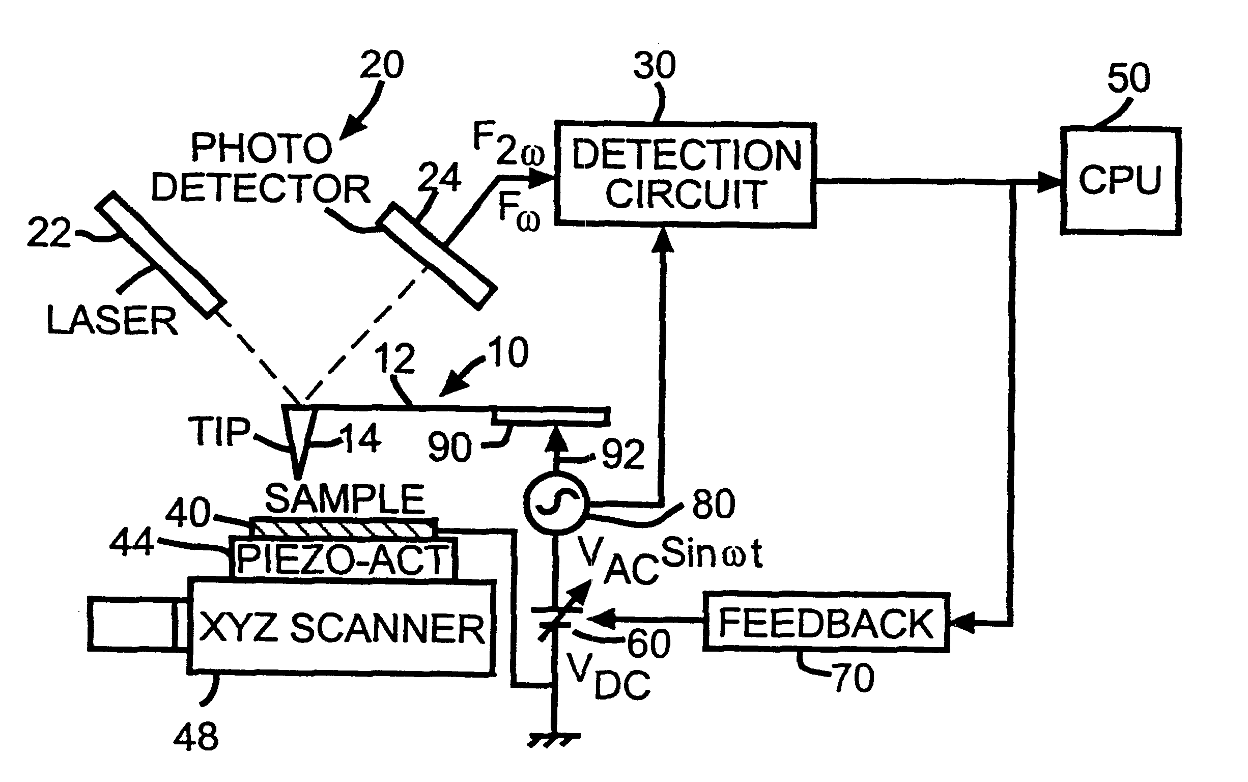
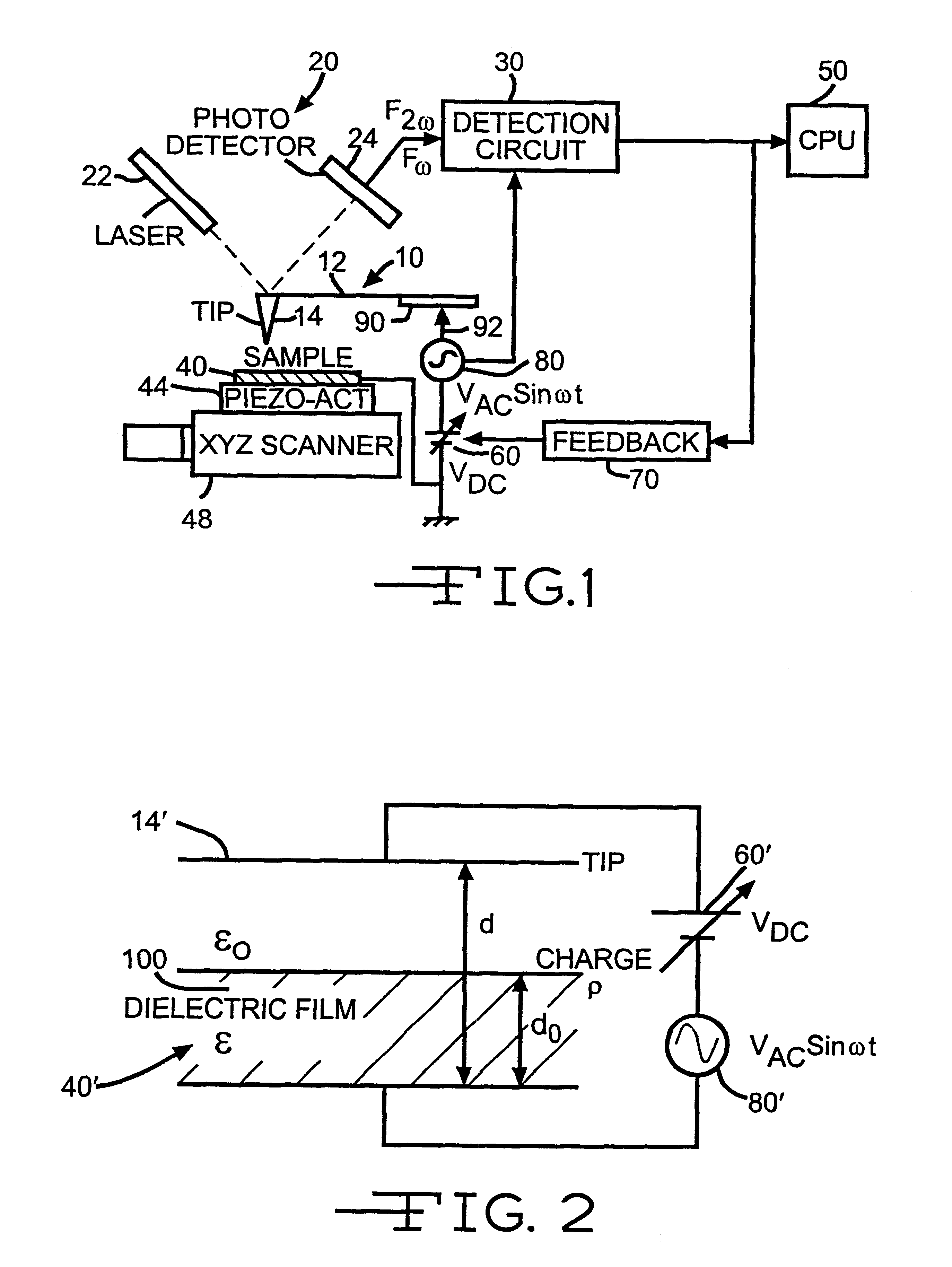
A representative configuration of an electrostatic microscope to which the present invention is applicable is shown is FIG. 1. The system consists of a fine detector with cantilever generally designated 10 and comprising an arm 12 and a needle or tip 14, an optical system 20 comprising laser 22 and photodetector 24, a detection circuit 30, a sample 40 under test operatively associated with an actuator 44 such as a piezoelectric driver which, in turn, is operatively associated with a scanner 48 for the actuator 44, a processor 50 connected to the output of detection circuit 30, a controllable source 60 of direct voltage, a feedback circuit 70 having an input connected to the output of detection circuit 30 and an output connected in controlling relation to d.c. source 60, and an a.c. source 80. The sample 40 under test is connected between d.c. source 60 and an electrical ground or reference. The combination of d.c. source 60 and a.c. source 80 is connected to detector arm 12 and to d...


PUM


Abstract

An electrostatic force microscope for measuring electrostatic force of a sample under test including a detector comprising a cantilever arm having a tip formation at one end and located so that electrostatic force is induced at the tip due to electrostatic charge on the sample under test, an optical system for transforming bending of the cantilever arm due to electrostatic force induced at the tip into an electrical signal containing a frequency component of the electrostatic force induced at the detector tip, a source for applying bias voltage to the detector, a detector for detecting the frequency component of the electrostatic force induced at the detector tip so that a measurement of electrostatic force on the sample under test can be obtained, and an electrostatic shield operatively associated with the cantilever arm. The shield is located between the cantilever arm and the sample under test, in particular in close spaced relation to the arm. The cantilever arm and the shield are maintained at the same electrical potential so that lines of electrostatic force are terminated at the shield.

Description

Hard copies with higher spatial resolution and better quality full color pictures are always expected in electrophotography technology. The photoreceptor is a key device to acquire the high quality hard copies. While on the one hand it is required to make a precise measurement of charge distribution on a photoreceptor drum, on the other hand the spatial resolution of currently available apparatus is fairly low. Charge distribution measurement with a very high spatial resolution is required both in electrophotography and in semiconductor research. It would be desirable to realize a measurement system which enables the charge distribution measurement to have a spatial resolution less than 10 .mu.m in diameter with utilizing the electrostatic force. Laser printers may already have the spatial resolution of 600 dpi or higher, which indicates that each pixel has approximately 21 .mu.m in diameter. Studies have been made relating to the scanning electrostatic force microscope, however, th...

Claims


Application Information

Patent Timeline
IPC IPC(8): G12B21/00G12B21/12G12B21/02G01BG01B7/06G01R29/12G01Q20/00G01Q60/30G01R
CPCB82Y35/00G01Q60/30Y10S977/864Y10S977/852
Inventor UEHARA, TOSHIOITOH, AKIYOSHINAKAGAWA, KATSUJITANI, MANABUWILLIAMS, BRUCE T.
Owner TREK BICYCLE CORPORATION
Why Eureka
Try Eureka