Magnetic float type flowmeter

a flowmeter and magnetic float technology, applied in the direction of direct mass flowmeters, volume/mass flow by dynamic fluid flow effect, liquid/fluent solid measurement, etc., can solve the problems of expensive items, unfavorable operation of flowmeters, and complicated construction of flowmeters

Inactive Publication Date: 2002-01-22
NMF
View PDF6 Cites 31 Cited by
  • Summary
  • Abstract
  • Description
  • Claims
  • Application Information

AI Technical Summary

Benefits of technology

The object of the present invention is to provide a new and improved magnetic mass and volume flow meter, which sufficiently reduces or overcomes the above-mentioned drawbacks of the known in the art magnetic flow meters, while preserving their advantages.
In particular, the main object of the present invention is to provide a new and improved mass and volume magnetic flow meter which has simple construction, is inexpensive and which is capable to measure wide range of flow rate.

Problems solved by technology

Unfortunately, their construction is rather complicated and they are expensive items.
Furthermore, operating of this instrument is not convenient, since it requires pre-establishing of dedicated calibration curve for each fluid, to be measured and therefore it is not possible to work with a single, universal calibration curve.
Since it employs optical sensor it requires that the measuring tube be made of transparent material and therefore the operation is limited strictly to measurement of flow rate of transparent fluids.
The other disadvantage of this flow meter is associated with the configuration of its magnetic means, consisting of a coil, wound around the core.
Besides, since the above construction of the magnetic means does not prevent the ball from reciprocating motion and therefore the measurement is less accurate.
Nevertheless, it has the same intrinsic disadvantages as the above-described flow meter, since it also employs magnetic means, which is configured as a coil wound around a dedicated core.

Method used


Image

  • Magnetic float type flowmeter
  • Magnetic float type flowmeter

Examples


Embodiment Construction

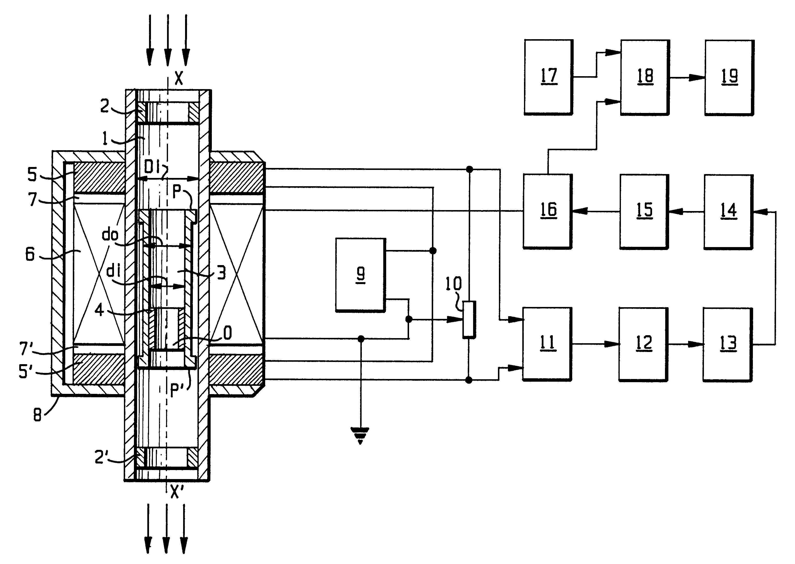
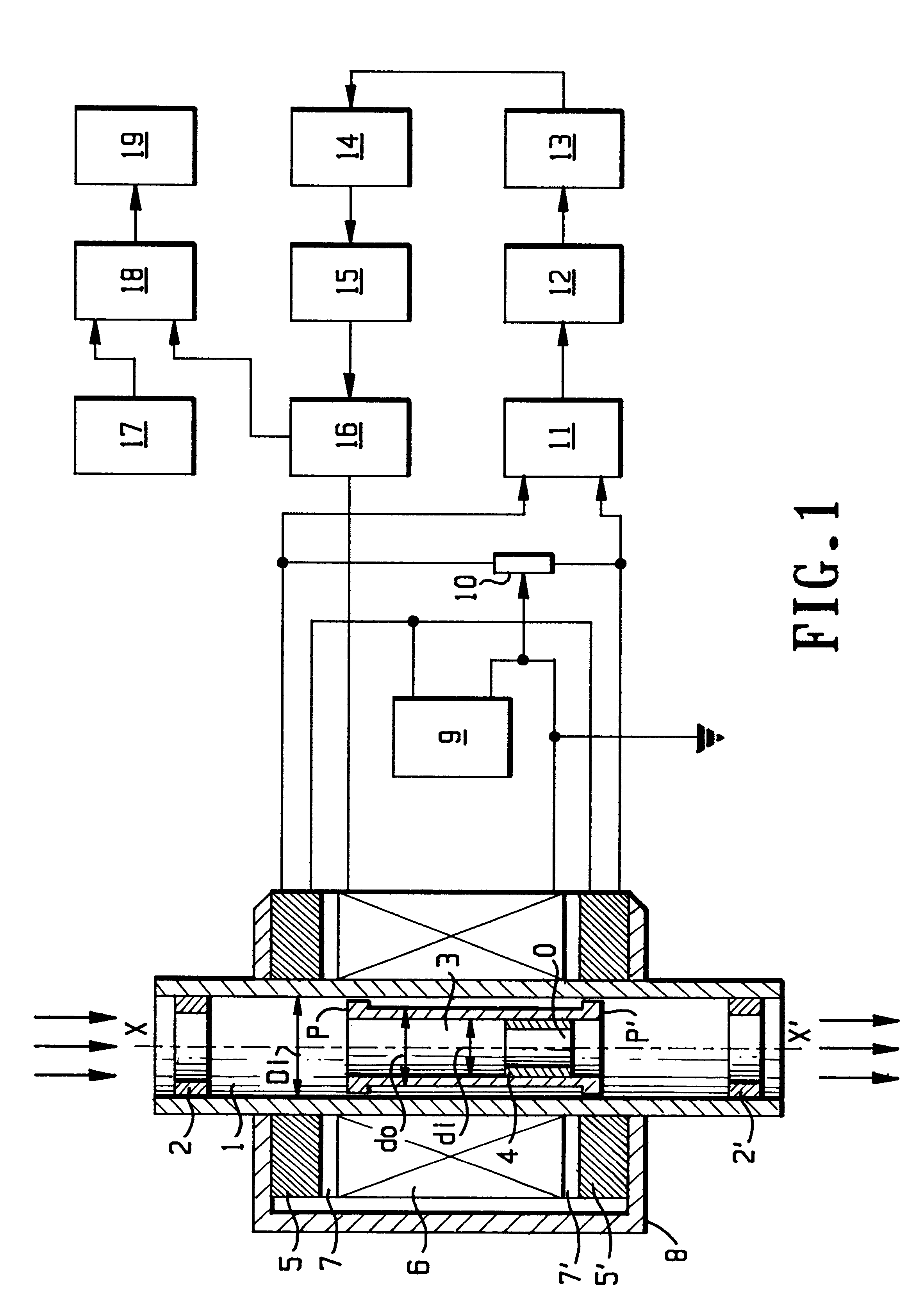
With reference to FIG. 1 the mechanical portion of the flow meter of the invention comprises an elongated tubular conduit 1, through which continuously flows the fluid as shown by arrows. The conduit is made of a non-ferromagnetic material and is configured as vertically directed cylinder with known inside diameter D.sub.i. In the upper and lower extremities of the conduit are arranged respective upper and lower ring-like stoppers 2,2', which allow the fluid to enter and to exit the interior of the conduit. Residing within the conduit is provided a float member 3, which can be displaced along the conduit's interior between the upper and lower stopper. The float member is formed as elongated cylinder, having its respective inside and outside diameter d.sub.i, d.sub.o. An exchangeable insert 4 might be deployed within the float member so as to vary the inside diameter, through which the fluid flows. The insert tightly seats within the float member and has calibrated orifice of known i...


PUM


Abstract

The present invention relates to magnetic flow meters comprising a floating member, made of magnetically responsive material and residing within a tubular conduit, through which the fluid flows. The flow meters are provided with a means for producing magnetic field in the conduit. A response signal is generated upon displacement of the float member within the magnetic field by the flowing fluid. Flow rate value is obtained by processing the response signal and comparing it with a calibration curve.

Description

The present invention refers to flow meters, suitable for measuring, monitoring and controlling of volume or mass flow rate of various gaseous or liquid fluids or streams of particulate materials.More particularly the present flow meter refers to so-called magnetic flow meters, employing a floating member, made of magnetically responsive material and residing within a tubular conduit, through which the fluid flows. Such flow meters are provided with a means for producing magnetic field in the conduit and they generate a response signal upon displacement of the float member within the magnetic field by the flowing fluid. Flow rate value is obtained by processing the response signal and comparing it with the a calibration curve.There are known various flow meters, which have been devised for measuring of flow rate and which are based on various physical principles.For example so-called Coriolis flow meter employ a sensor tube, through which the fluid flows and twists the tube. This tw...

Claims


Application Information

Patent Timeline
Patent Type & Authority Patents(United States)
IPC IPC(8): G01F1/28G01F1/20G01F1/24G01F1/78
CPCG01F1/28G01F1/24
Inventor NATAPOV, VLADIMIR
Owner NMF
Why Eureka
Try Eureka