Collapsible impulse radiating antenna

a radiating antenna, collapsible technology, applied in the direction of antennas, basic electric elements, electrical appliances, etc., can solve the problems of compromising the available gain, clumsy deployment and transportation, and the antenna described is not applicable for a large bandwidth or ultra-wide band use,

Inactive Publication Date: 2002-01-22
BOWEN LELAND H +1
View PDF12 Cites 119 Cited by
  • Summary
  • Abstract
  • Description
  • Claims
  • Application Information

AI Technical Summary

Benefits of technology

FIGS. 20a through 20h show the IEEE gain plotted as a function of the angle off-boresight in the H-plane for the ultra-lightweight configuration of the CIRA of the present invention acquired with the data acquisition system of FIG. 15 with the FRI-TEM-02-100 sensor of FIG. 16a, wherein plots are provided at 98 MHz, 195 MHz, 391 MHz, 586 MHz, 781 MHz, 977 MHz, 2,002 MHz, and 4,004 MHz;
FIGS. 21a through 21h show the IEEE gain plotted as a function of the angle off-boresight in the E-plane for the ultra-lightweight configuration of the CIRA of the present invention acquired with the data acquisition system of FIG. 15 with the FRI-TEM-02-100 sensor of FIG. 16a, wherein plots are provided at 98 MHz, 195 MHz, 391 MHz, 586 MHz, 781 MHz, 977 MHz, 2,002 MHz, and 4,004 MHz;
FIG. 22 is the antenna pattern based on peak raw voltage measurements in the H-plane as a function of the angle off-boresight of the ultra-lightweight configuration of the CIRA of the present invention acquired with the data acquisition system of FIG. 15 with the FRI-TEM-02-100 sensor of FIG. 16a;
FIG. 23 is a plot of raw voltages at several angles in the H-plane as a function of time of the ultra-lightweight configuration of the CIRA of the present invention acquired with the data acquisition system of FIG. 15 with the FRI-TEM-02-100 sensor of FIG. 16a;
FIG. 24 is the antenna pattern based on peak raw voltage measurements in the E-plane as a function of the angle below boresight of the ultra-lightweight configuration of the CIRA of the present invention acquired with the data acquisition system of FIG. 15 with the FRI-TEM-02-100 sensor of FIG. 16a;
FIG. 25 is a plot of raw voltages at several angles in the E-plane as a function of time of the ultra-lightweight configuration of the CIRA of the present invention acquired with the data acquisition system of FIG. 15 with the FRI-TEM-02-100 sensor of FIG. 16a;

Problems solved by technology

IRAs are generally fabricated from a solid reflector, which is clumsy to deploy and transport particularly when it reaches a certain size.
None of these patents include the features of a broadband feed enabling a broad bandwidth for the antenna, collapsibility, and portability.
The antenna described is not applicable for a large bandwidth or for ultra-wide band use; the reflector is flat and cannot achieve a paraboloidal shape thereby compromising the available gain.
None of the antennas described in the above patents provide a lightweight, portable, ultra-wideband collapsible antenna.

Method used


Image

  • Collapsible impulse radiating antenna
  • Collapsible impulse radiating antenna
  • Collapsible impulse radiating antenna

Examples


second embodiment

Attention is returned to FIGS. 11-14 which provide further detail of the present invention which is a multifunction version of CIRA 10 described above, and is referred to herein as CMIRA 100. Reflector 102 of CMIRA 100 has an adjustable surface curvature and therefore has an adjustable beamwidth. It is to be understood that although two modes, focused and defocused, are discussed herein, CMIRA 100 can of course accommodate varying degrees of focus depending upon the degree of expansion of reflector 102 via expandable seams 106 discussed below. It is also to be understood that CMIRA 100 comprises the identical elements and operates in the identical fashion as CIRA 10 described above, but includes expandable seams in reflector 102 and feed arms 104. All alternative and equivalent elements described with regard to CIRA 10 are equally applicable to CMIRA 100. FIG. 11a shows CMIRA 100 in the deployed focused mode. When in the focused mode, reflector 102 of CMIRA 100 is a paraboloid and o...

example

Both the CIRA and CMIRA embodiments were tested using standard time domain antenna range techniques, and the results were converted to IEEE standard gain in the frequency domain. Two CIRA configurations were tested, an ultra-lightweight configuration having twelve triangular panels and a twenty-panel configuration. One CMIRA configuration was tested, having twenty panels, in both the focused and defocused modes.

Normalized Impulse Response

First, a review of the parameters used to describe antennas is provided. Antennas are described in the time domain with an impulse response, of the form h.sub.N (t). In transmission mode, the antenna radiates a field on boresight, E.sub.rad (t), which is described by equation (6.5) in E. G. Farr and C. E. Baum, Time Domain Characterization of Antennas with TEM Feed, Sensor and Simulation Note 426, October 1998, the content of which is incorporated herein by reference: ##EQU1##

where Z.sub.o is the impedance of free space, Z.sub.c is the impedance of ...


PUM


Abstract

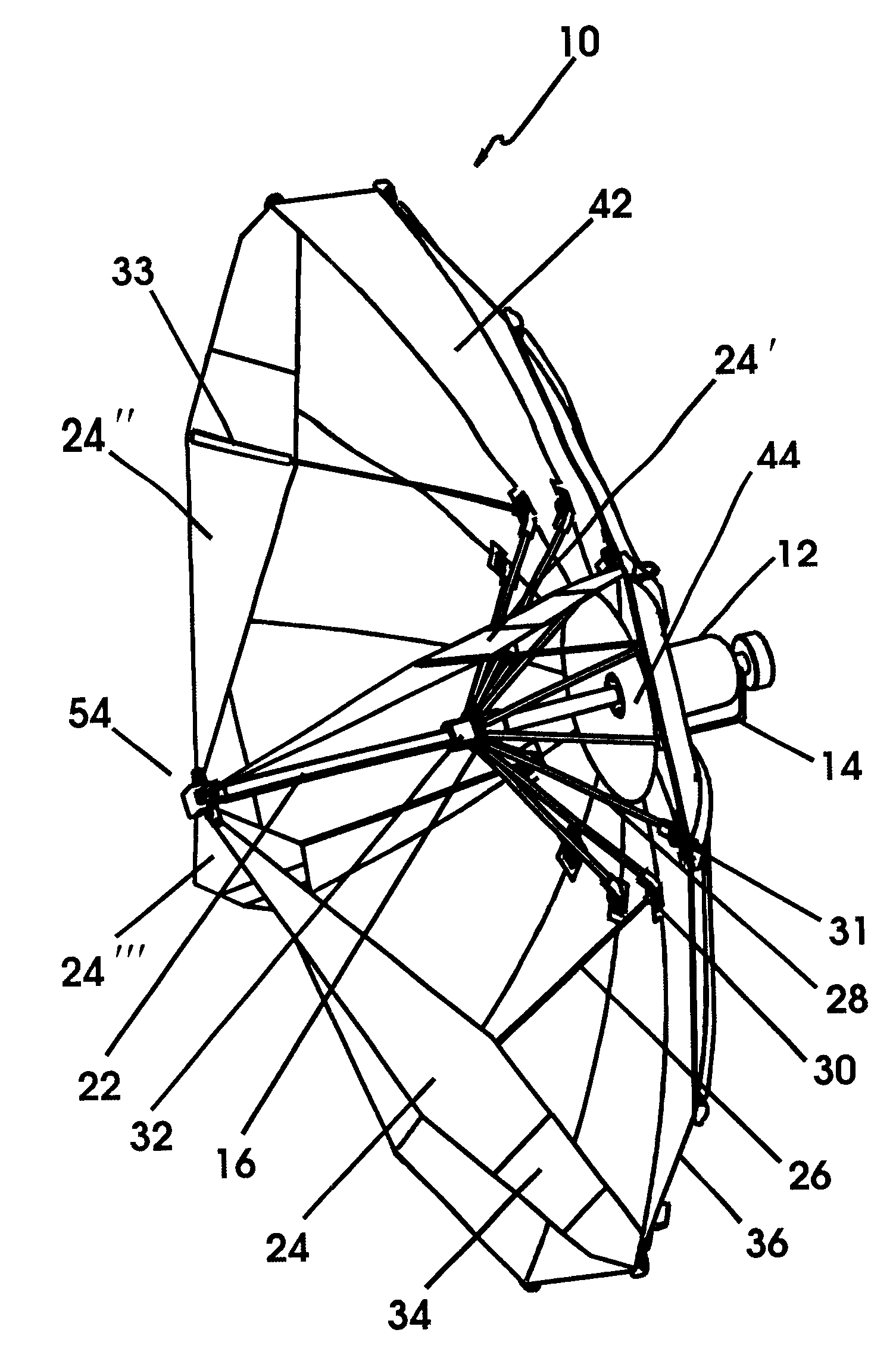
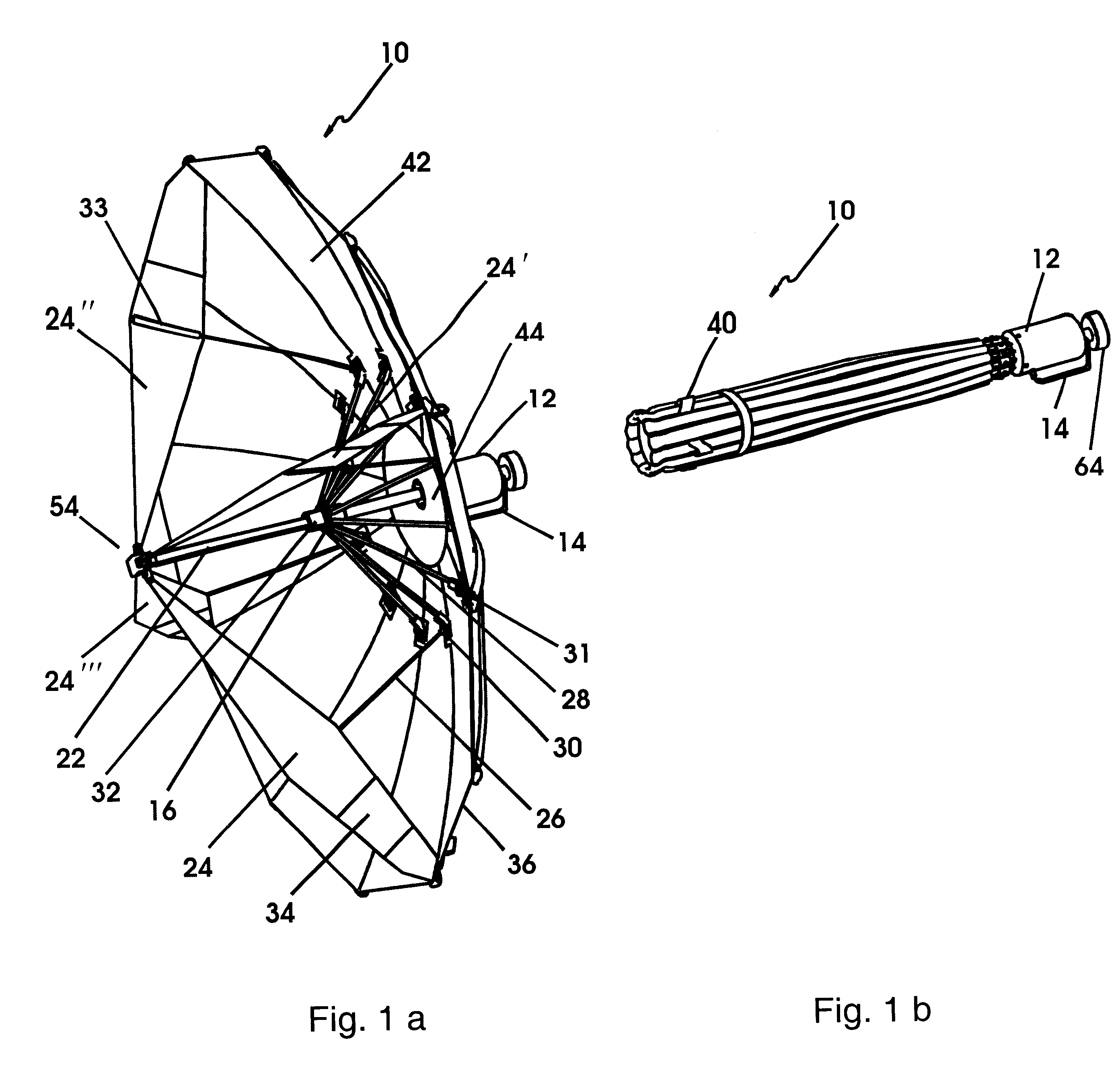
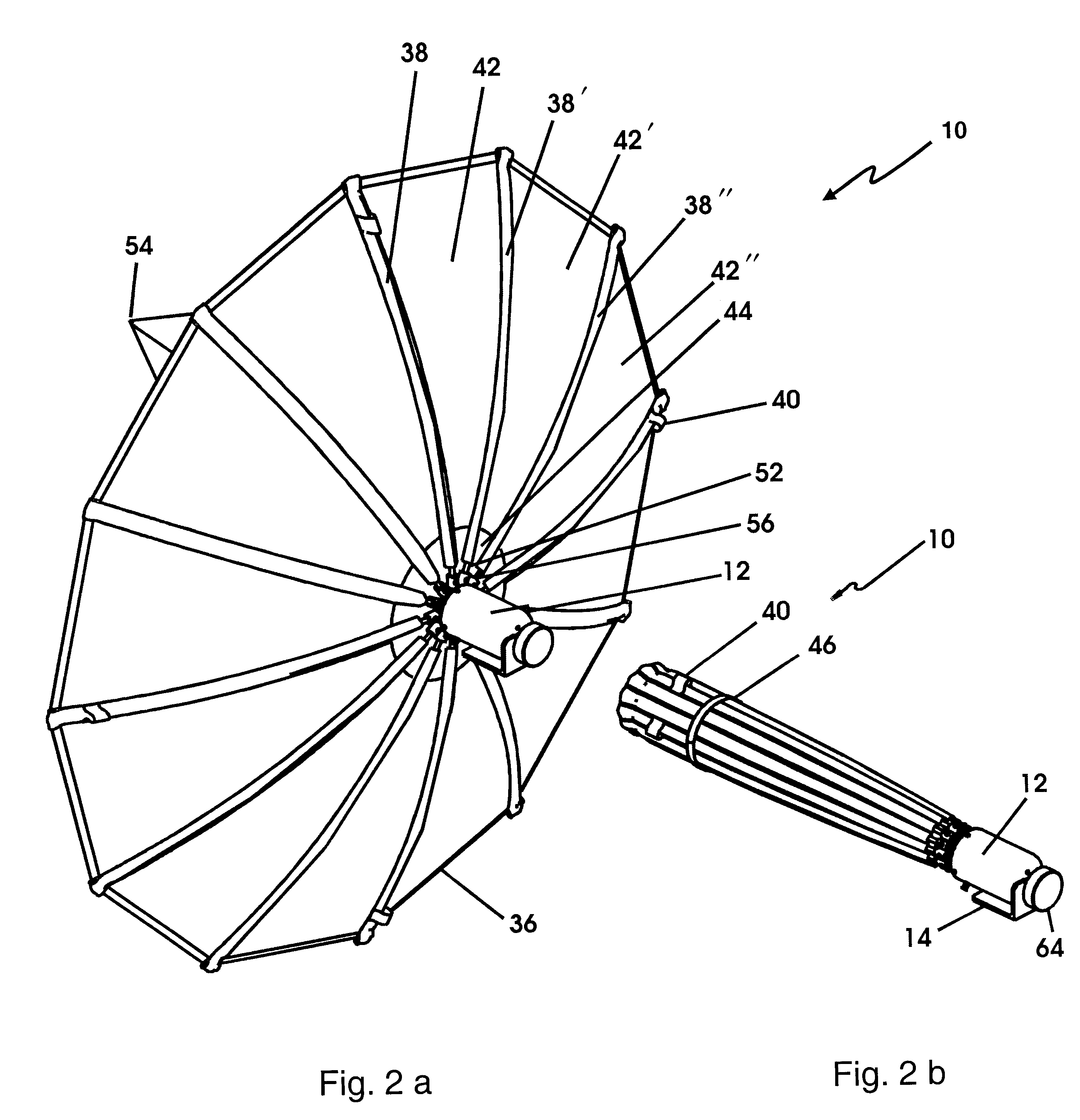
A broadband collapsible impulse radiating antenna having a reflector 36 and feed arms 24 made from a flexible conductive material. An umbrella-like support mechanism is used to collapse and deploy reflector 36. The umbrella-like mechanism consists of a plurality of support ribs 52, a center support rod 22, center push rods 28, feed arm support rods 26, and push sleeve 32. Support ribs 52 are attached to the reflector 36 and are pivotally connected to a central hub 66. Push sleeve 32 slides along center support rod 22 causing the radial center push rods 28 to provide a radial force to reflector 36 and thereby deploy and collapse the antenna. Center can 12 contains center support rod 22 and an RF splitter 86 that splits the input signal into two feed cables of equal length leading to the feed point 54. Optional expandable seams can be provided in the reflector and feed arms so that the surface curvature of the reflector can be adjusted.

Description

1. Field of the Invention (Technical Field)The present invention relates to the field of impulse radiating antennas, specifically to wideband collapsible and portable impulse radiating antennas for ease of transport and deployment in the field.2. Background ArtNote that the following discussion refers to a number of publications by author(s) and year of publication, and that due to recent publication dates certain publications are not to be considered as prior art vis-a-vis the present invention. Discussion of such publications herein is given for more complete background and is not to be construed as an admission that such publications are prior art for patentability determination purposes.The present invention is a collapsible impulse radiating antenna ("CIRA"), which is a compact and lightweight implementation of the general class of antennas known as impulse radiating antennas (IRAs). IRAs are well suited for radiating an extremely broad band of signal frequencies at reasonable ...

Claims


Application Information

Patent Timeline
Patent Type & Authority Patents(United States)
IPC IPC(8): H01Q15/14H01Q15/16
CPCH01Q15/161Y10S343/02
Inventor BOWEN, LELAND H.FARR, EVERETT G.
Owner BOWEN LELAND H
Why Eureka
Try Eureka