Device for administrating electro-muscle stimulation and method of use

a technology of electromuscle stimulation and electrodes, which is applied in the direction of therapy, physical therapy, artificial respiration, etc., can solve the problems of paralysis of the legs walking the exercycle, and achieve the effects of enhancing natural exercise, prolonging the exercise period, and promoting maximum muscle contraction

Inactive Publication Date: 2002-01-22
VECTOR INT
View PDF6 Cites 157 Cited by
  • Summary
  • Abstract
  • Description
  • Claims
  • Application Information

AI Technical Summary

Benefits of technology

The present invention is directed to a device for administrating electro-muscle stimulation (EMS) which comprises a flexible covering containing positionable electrodes which are strategically placed upon a patient's body to stimulate specific muscles or muscle groups. In a preferred embodiment, the covering is in the form of a belt or band which is snugly wrapped around a portion of the patient's body. The belt is typically used in conjunction with an EMS machine which emits an electrical voltage/current for activating the electrodes. The electrodes in turn cause the selected muscles to contract. By placing the electrodes in specific locations within the belt, and corre

Problems solved by technology

This causes pedaling of the ex

Method used


Image

  • Device for administrating electro-muscle stimulation and method of use
  • Device for administrating electro-muscle stimulation and method of use
  • Device for administrating electro-muscle stimulation and method of use

Examples


second embodiment

FIG. 6 is a top plan view of two extremity cuff devices 20 of the second embodiment shown in FIG. 3 traversely joined together. One device 20 receives a positive stimulation signal 34, and the other receives a negative (return or common) stimulation signal 38. The cooperating positive and negative signals are required in order to promote a current flow between electrodes 22 of the two devices 20.

FIG. 7 is a front elevation view of a patient 506 showing the muscles of the rectus abdominus divided at the umbilical area 512 into an upper portion 508 and a lower portion 510. The rectus abdominus includes two distinct muscles on opposite sides of the linea alba. But for purposes of this invention, they work together and are stimulated together. Line 514 defines the junction of the right and left obliques 516 with the upper portion 508 and lower portion 510 of the rectus abdominus (refer also to FIG. 8).

FIG. 8 is a side elevation view of the patient 506 showing the right obliques 516. The...

embodiment 120

FIG. 12 is a side elevation view of the abdominal embodiment 120 installed on an exercising patient 506. Device 120 stimulates the muscles as was described under the discussion of FIG. 9.

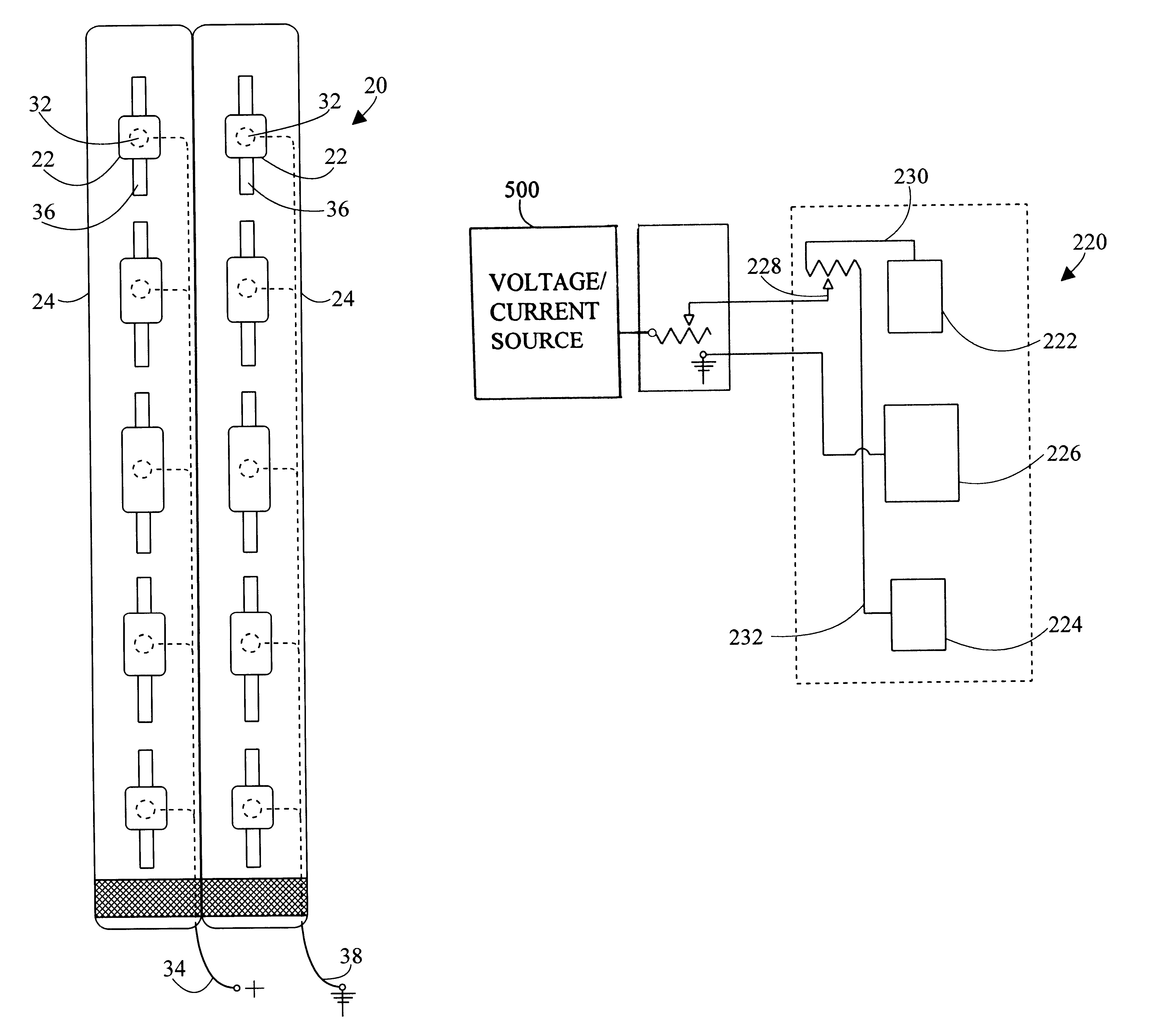
FIG. 13 is a top plan view of a third extremity cuff embodiment, generally designated as 220, having both poles on one belt. FIG. 14 is a schematic diagram of the third extremity cuff embodiment 220. Third extremity cuff 220 includes a first positive electrode 222 and a second positive electrode 224. A return electrode 226 is disposed between first positive electrode 222 and second positive electrode 224. An adjustment control 228 simultaneously applies a first positive voltage 230 to first positive electrode 222 and a second positive voltage 232 to second positive electrode 224. As first positive voltage 230 increases, second positive voltage 232 decreases. And as first positive voltage 230 decreases, second positive voltage 232 increases. That is, adjustment control 228 functions much as the balan...

embodiment 420

FIG. 17 is a bottom plan view of fifth extremity cuff Holes 453 are cut in flexible covering 423 directly over sponges 429 so that sponges 429 may come into contact with the user's skin. The snaps 449 hold the edges of the sponges 429 to keep them from passing through the holes 453.

FIG. 18 is a top plan view of fifth extremity cuff embodiment 420 in the folded and ready for use configuration. From FIG. 16, the left side has been folded under the right side in direction 458 generally along axis 460. Stretchable zigzag stitching 465 is used to form flexible covering 423 into an elongated pocket into which sponge assembly 425 can slidably fit. Flap 438 has been folded over in direction 470 to close the open end of the pocket.

FIG. 19 is a cross sectional view along the line 19--19 of FIG. 18 showing the folded and sewn flexible covering 423.

FIG. 20 is a schematic diagram of fifth extremity embodiment 420. Master adjustment control 404 and balance adjustment control 428 are both mounted...


PUM


Abstract

A device for administrating electro-muscle stimulation (EMS) includes a flexible covering having a plurality of spaced apart electrodes (22). In a preferred embodiment the flexible covering is shaped like a belt (24) and is designed to encircle and be connected around a portion of a patient's body (506). The belt is fabricated from an elastic material so that the electrodes are pressed against the skin of the patient to promote better electrical conduction. The electrodes are selectively positionable to different locations on the belt, so they may be placed directly over a selected muscle or muscle group. Each electrode has its own individual control (32) for adjusting the level of the electrical stimulation signal, so that (1) different muscles can receive different levels of stimulation, and (2) the level of stimulation may be changed during the course of treatment. A master adjustment control (504) is used to adjust the stimulation signal level applied to all the electrodes. In a preferred embodiment, the individual adjustment controls are located adjacent their respective electrodes on the belt. In accordance with another preferred embodiment of the invention, the flexible covering (423) is folded to form a pocket, and a sponge assembly (425) is removably inserted into the pocket. The sponge assembly has a plurality of replaceable sponges (429).

Description

The present invention relates generally to electro-muscle stimulation, and in particular to a belt-like device which is wrapped around or otherwise placed upon a portion of the body to administer adjustable levels of electrical stimulation.Electro-muscle stimulation (EMS) is well known in the medical art. This technology utilizes a conductive pad or electrode to externally apply a very weak current to a muscle or group of muscles and thereby cause them to contract. The electrode receives an electric stimulation signal from an external voltage / current source, such as an EMS machine. The stimulation signal can be adjusted in amplitude, polarity, frequency, waveform, etc. EMS is commonly used in physical or occupational therapy to strengthen atrophied muscles or paralyzed limbs, and also to exercise muscles that are immobilized for long periods of time as a result of muscular or neurological disorders, extended periods of bed rest arising from injury, surgery, or illness. EMS is also u...

Claims


Application Information

Patent Timeline
IPC IPC(8): A61N1/36A61N1/04
CPCA61N1/0452A61N1/0476A61N1/36014A61N1/36003A61N1/0484
Inventor HURTADO, ARTHUR F.
Owner VECTOR INT
Why Eureka
Try Eureka