

Seat weight measuring apparatus
- Summary
- Abstract
- Description
- Claims
- Application Information
AI Technical Summary
Benefits of technology
Problems solved by technology
Method used
Image

Examples
Embodiment Construction
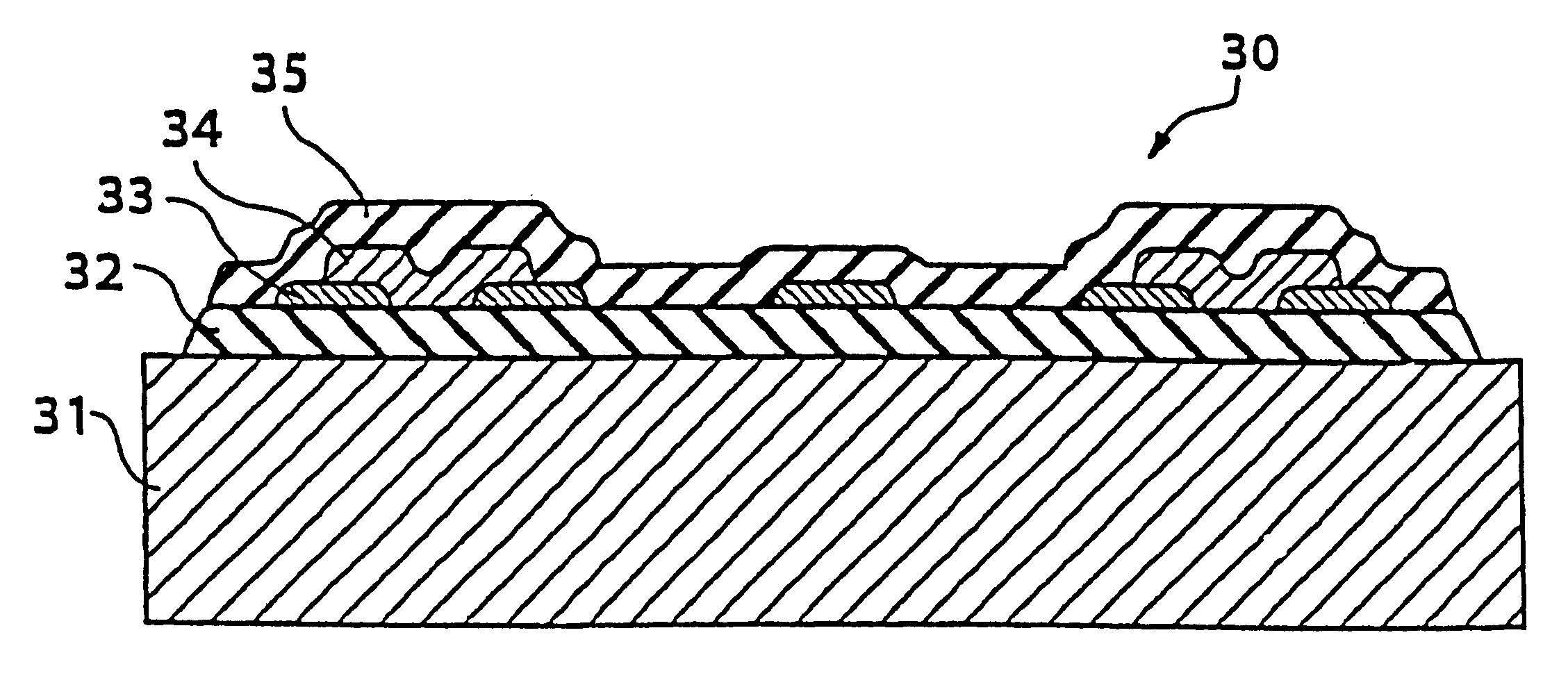
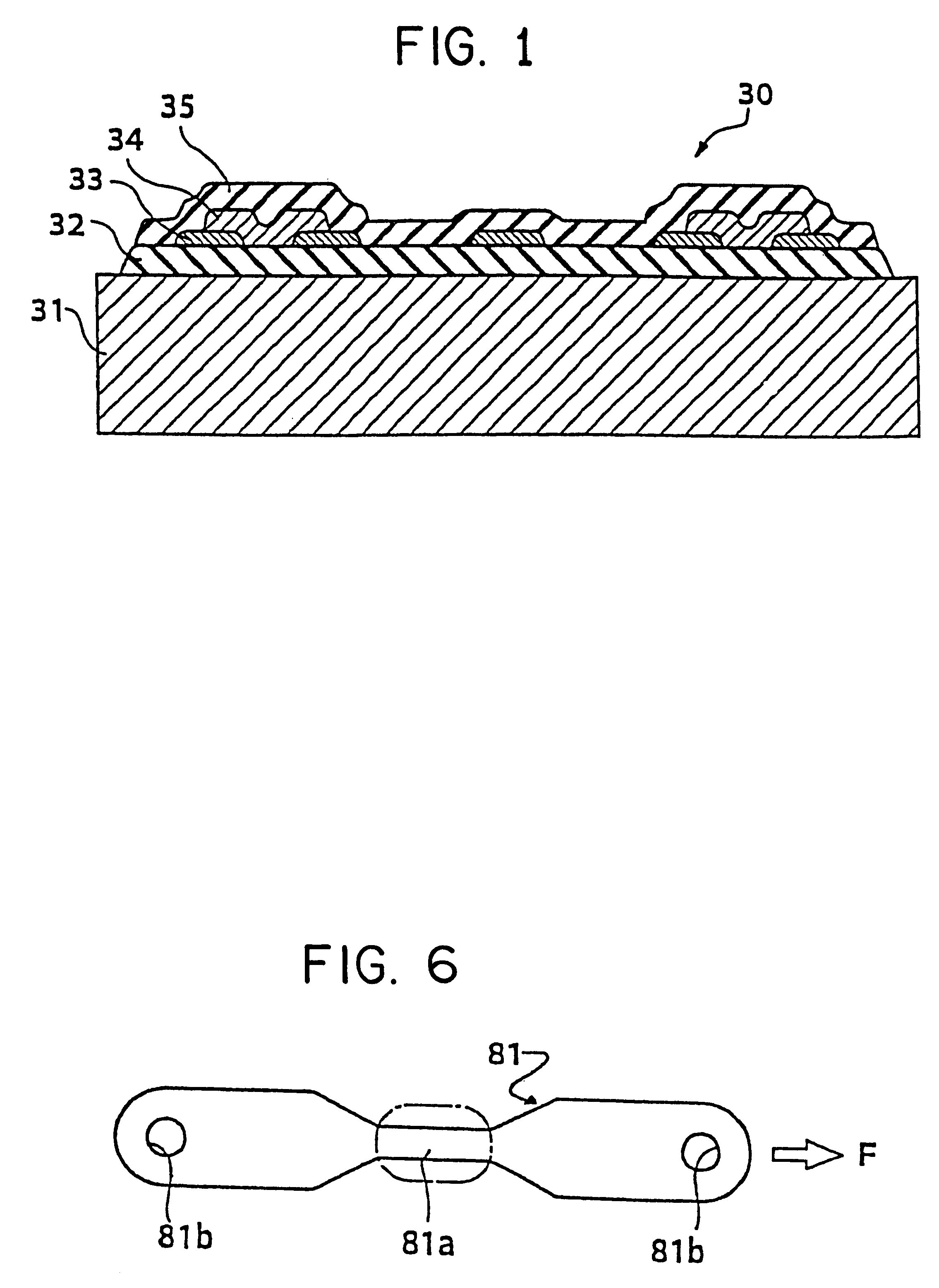
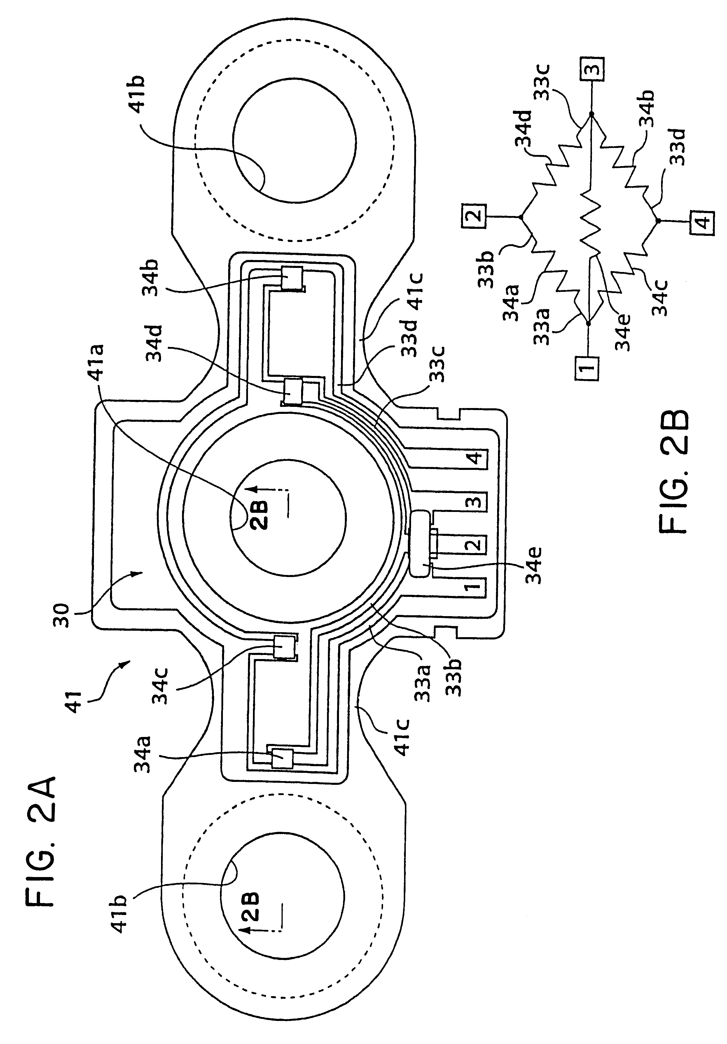
A seat weight measuring apparatus of the present invention is an apparatus for measuring the weight of the vehicle seat including the weight of a passenger sitting thereon and is characterized by comprising: a load sensor disposed inside the seat or between the seat and a vehicle body for receiving at least a part of the seat weight and converting the weight into an electrical signal, wherein the load sensor has a sensor member which is elastically deformable when received at least a part of the seat weight, and a strain gauge arranged on a surface of the sensor member, wherein the strain gauge includes a lower insulating layer, a wiring layer, a resistor layer, and an upper insulating layer, which are sequentially and selectively formed on the sensor member.
Due to its laminated construction, the strain gauge can be formed, for example, by printing, thus improving productivity. The strain gauge is formed directly on the sensor member, thereby facilitating the assembly working. In ad...
PUM
 Abstract
Description
Claims
Application Information