Low-current sample rate converter

Inactive Publication Date: 2002-02-12
QUALCOMM INC
View PDF4 Cites 27 Cited by
  • Summary
  • Abstract
  • Description
  • Claims
  • Application Information

AI Technical Summary

Problems solved by technology

However, this method often results in undesirable signal distortion introduced by the DAC during signal reconstruction and by quantization effects during analog-to-digital conversion.
Consequently, most of the filter computations including multiplications and additions result in zeros, representing wasted power.
This represents additional filter inefficiency.
The high sampling rate results in large power consumption.
The requirement often results in computationally inefficient, space inefficient, and energy inefficient sample rate converters.
These disadvantages are

Method used


Image

  • Low-current sample rate converter
  • Low-current sample rate converter
  • Low-current sample rate converter

Examples


Embodiment Construction

While the present invention is described herein with reference to illustrative embodiments for particular applications, it should be understood that the invention is not limited thereto. Those having ordinary skill in the art and access to the teachings provided herein will recognize additional modifications, applications, and embodiments within the scope thereof and additional fields in which the present invention would be of significant utility.

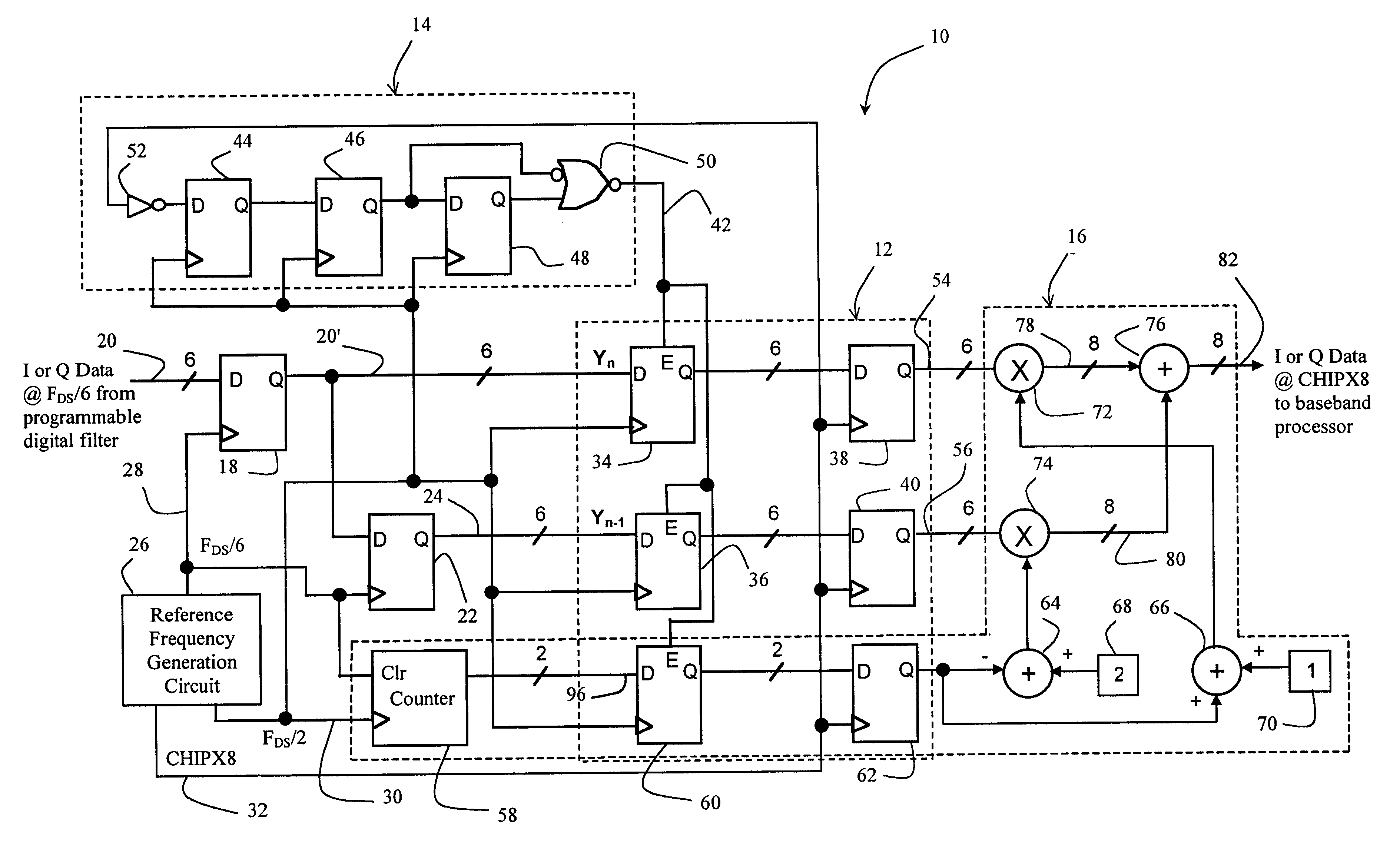
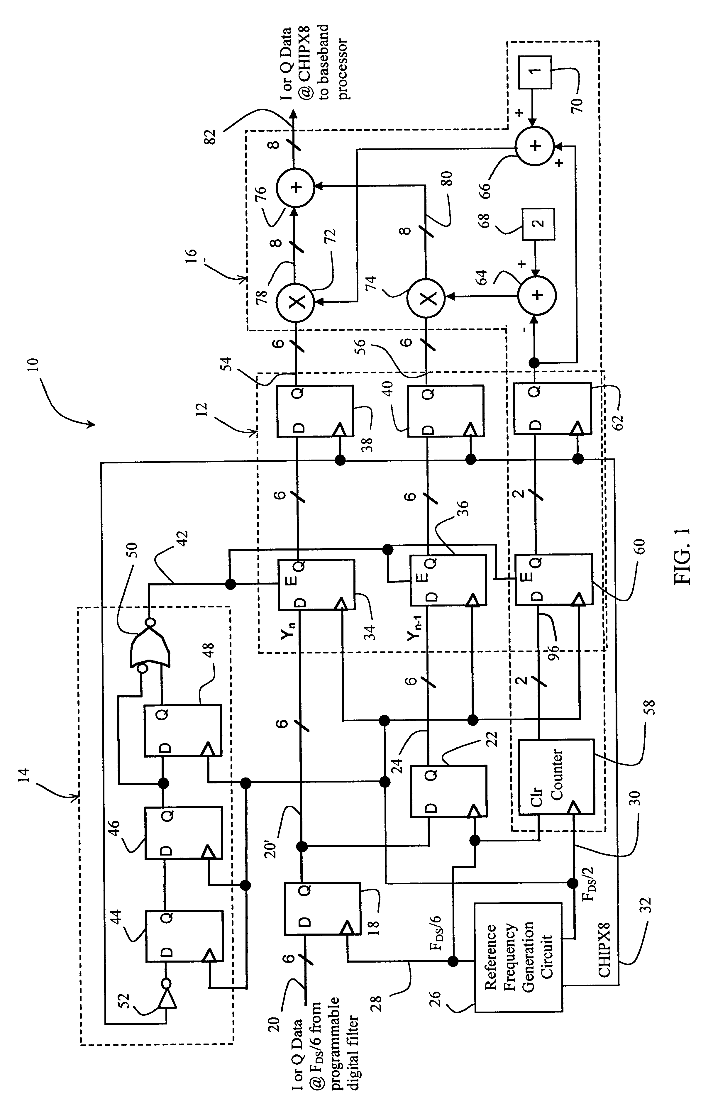
FIG. 1 is a diagram of a sample rate converter constructed in accordance with the teachings of the present invention. The converter 10 includes a sample rate conversion circuit 12, a sample rate conversion enable circuit 14, and a low-pass filter circuit 16. A first register 18 provides a Y.sub.n input 20 to the rate conversion circuit 12. In-phase (I) or quadrature (Q) data output from a programmable digital filter (as discussed more fully below) provides input to the first register 18 at a sample rate of F.sub.-- / 6. A second register 22 ...


PUM


Abstract

A low power sample rate converter adapted for use with a telecommunications system transceiver. The sample rate converter includes a first circuit that provides an input signal characterized by a first sample rate and a delayed version of the input signal. A second circuit periodically multiplies, at a second sample rate, samples in the input signal by a first predetermined coefficient in accordance with a predetermined transfer function and provides a first signal in response thereto. A third circuit periodically multiplies, at the second sample rate, samples in the delayed version of the input signal by a second predetermined coefficient in accordance with the predetermined transfer function and provides a second signal in response thereto. A fourth circuit combines the first signal and second signal providing a rate-converted version of the input signal as an output signal in response thereto. In a specific embodiment, the delayed version of the input signal is delayed by one sample with respect to the input signal. The sample rate converter further includes a counter that is clocked by a first periodic signal. The first periodic signal has a frequency related to the first sample rate by a predetermined fraction. The counter is cleared by a second periodic signal having a second frequency equivalent to the first sample rate. The counter produces a counter output at the first frequency. In the preferred embodiment, the predetermined fraction is ⅓ and the first predetermined coefficient is equivalent to the sum of 1 and the counter output. The second predetermined coefficient is equivalent to the difference of 2 and the counter output. The fourth circuit includes an adder for adding the first signal and the second signal and providing the output signal in response thereto. The predetermined transfer function is represented by the following coefficient sequence: [1 2 3 2 1].

Description

1. Field of InventionThis invention relates to multi-rate digital signal processing systems. Specifically, the present invention relates systems for effecting sample rate conversion of a digital signal.2. Description of the Related ArtTelecommunications systems that transmit and receive different types of signals such as facsimile, speech and video signals must often process various signals at different rates commensurate with the bandwidths of the corresponding signals. The process of converting a signal from a given rate to a different rate is called sample rate conversion. Systems that employ multiple sampling rates in the processing of digital signals are called multi-rate digital signal processing systems.Multi-rate systems typically employ one of two general methods to effect sample rate conversion. One method involves passing the digital signal through a digital-to-analog converter (DAC) and then re-sampling the resulting analog signal at the desired rate via an analog-to-dig...

Claims


Application Information

Patent Timeline
IPC IPC(8): H03H17/06
CPCH03H17/0621H03H2218/04
Inventor MATHE, LENNARTMACEK, DANIEL T.
Owner QUALCOMM INC
Why Eureka
Try Eureka