
Filter circuit including system for tuning resonant structures to change resonant frequencies thereof

a filter circuit and filter structure technology, applied in the direction of resonant circuit details, generators/motors, waveguide types, etc., can solve the problems of not allowing the circuit to be tuned, no known method for tuning the frequency of mechanical resonators, and inability to undertake trimming

Inactive Publication Date: 2002-02-19
TWITTER INC
View PDF7 Cites 20 Cited by
  • Summary
  • Abstract
  • Description
  • Claims
  • Application Information

AI Technical Summary

Problems solved by technology

However, a problem arises in that, hitherto the present invention, there have been no known methods for tuning the frequency of the mechanical resonators.
While means for trimming the resonators exist, these trimming means and methods do not allow the circuit to be tuned over time due to temperature or other environmental conditions.
Other problems of the conventional systems and methods include that the trimming is a one-time event and cannot be undertaken once the device leaves the production facility.

Method used


Image

  • Filter circuit including system for tuning resonant structures to change resonant frequencies thereof
  • Filter circuit including system for tuning resonant structures to change resonant frequencies thereof
  • Filter circuit including system for tuning resonant structures to change resonant frequencies thereof

Examples


first embodiment

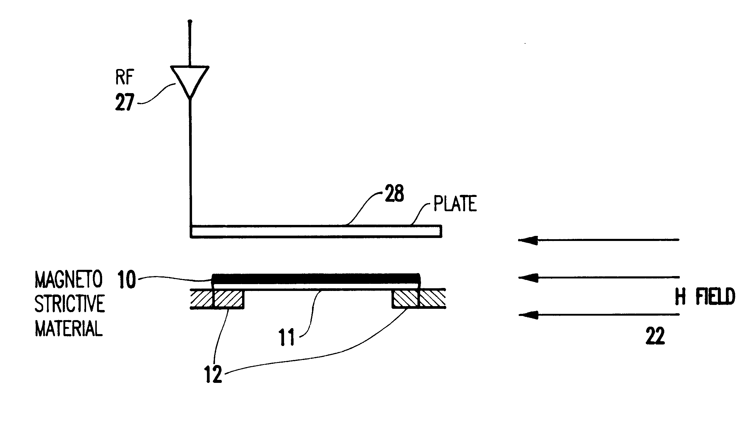
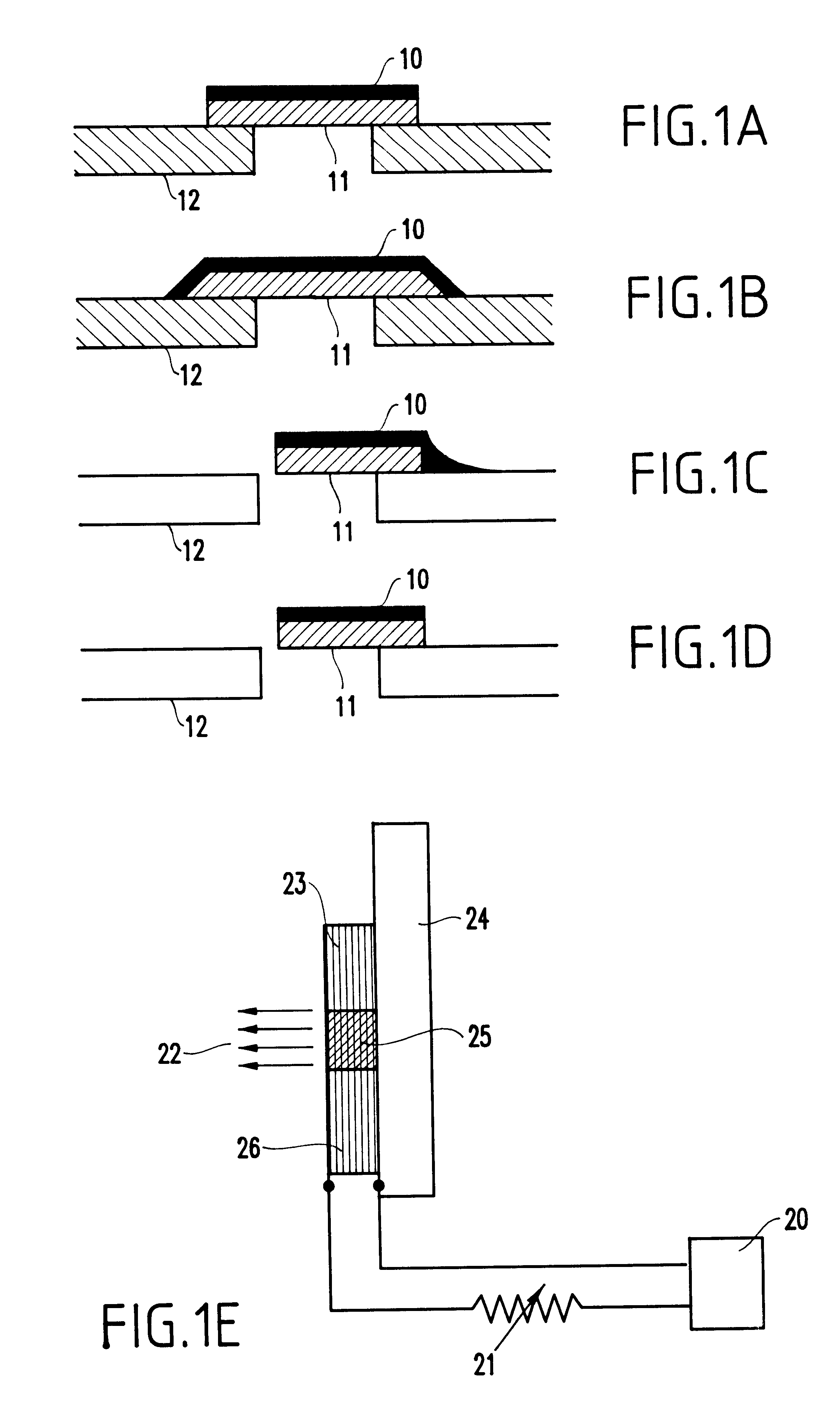
Turning now to FIGS. 1A-1F, a first embodiment will be described of the present invention. The present invention provides novel ways of tuning a resonant bar or cantilever 11, particularly those that are short along their major axis. This kind of bar or cantilever 11 resonator is particularly useful for telephony applications, but hitherto the invention, telephony applications utilizing these bar structures were too difficult to tune.

Thus, with the invention, for a fixed bar length, geometrical shape and thickness, there are well known sets of discrete and resonant frequencies that are proportional to the square root of the material's Young's modulus, E divided by the square root of the density times the reciprocal of the bar's length squared (e.g., see P. M. Morse, Vibration and Sound, Chapter IV, p. 151, McGraw-Hill, NY 1948).

To obtain tuning, a coating of a magnetostrictive film 10 is deposited (e.g., plated, vapor-deposited, ion bombarded, etc.) onto the resonant cantilever or b...

second embodiment

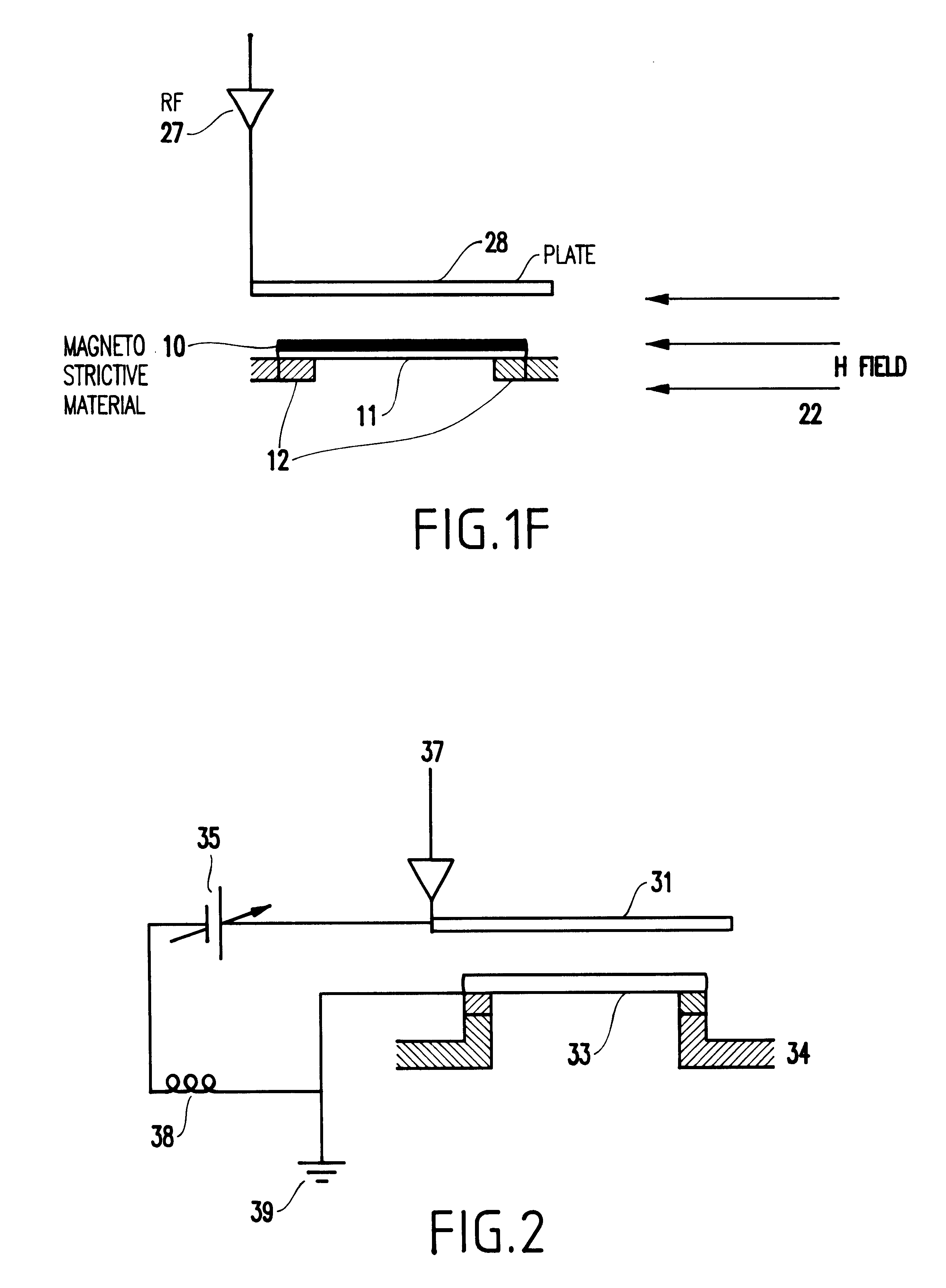
Referring to FIG. 2, a second embodiment of the invention will be described. The second embodiment of the invention uses the "Keyes effect", and is different from the first embodiment. It uses a single crystal semiconductor bar placed in an applied electric field, as opposed to the magnetic field of the first embodiment.

With this embodiment, it also becomes possible to tune the resonance of a bar or cantilever, here by causing changes in the elastic constants of a thin bar on the order of 1000 .ANG. or so. The Young's modulus E is proportional to the elastic constants so that the resonant frequency of the bar becomes dependent on the change in the elastic constants.

By applying a voltage to the electrode above and in close proximity to the cantilever, as shown in FIG. 2, the elastic constants change of a layer within the bar decreases in accordance with an effect known as the Keyes effect. To obtain this effect or change in elastic constants requires the use of single crystals (silic...


PUM


Abstract

A structure (and method) for tuning a resonant structure, includes a resonant structure including either a predetermined material coating provided on either a bar or a cantilever, or a lightly doped single crystal semiconductor material, and a circuit for providing a variable field adjacent the resonant structure, with the length or at least one of the elastic constants of the resonant structure changing with the application of the variable magnetic or electric field, respectively, thereby to selectively tune the resonant structure.

Description

1. Field of the InventionThe present invention generally relates to a method and system for tuning micro-electro mechanical (MEMS) cantilevers or bars to change their resonant frequency, and more particularly to a method and system for tuning cantilevers or bars which are part of a filter mechanism used in telephony and the like.2. Description of the Related ArtIn a variety of electrical applications, such as telephony for example, certain incoming frequencies must be filtered, allowing only certain pre-set or desired frequencies to pass into the main circuit. To accomplish this selective passage, a tuned filter circuit is typically used.In telephony (and other applications), extremely small filter circuits are used, some made by micro-electro mechanical means and devices. The filters contain mechanically resonant elements that vibrate when excited by their respective resonance frequency. When the applied frequency is off-resonance, there will be very little, if any, enhancement of ...

Claims


Application Information

Patent Timeline
Patent Type & Authority Patents(United States)
IPC IPC(8): H01L41/00H03H9/22H01L41/12H03H9/00H10N35/00
CPCH03H9/22H01L41/12H10N35/00
Inventor VON GUTFELD, ROBERT JACOBZIEGLER, JAMES F.
Owner TWITTER INC
Learn More