Container with integral module for heating or cooling the contents and method for its manufacture

a technology of container and contents, applied in the field of containers, can solve the problems of self-heating containers overheating, presenting a burn hazard, and consuming contents,

Inactive Publication Date: 2002-03-05
AURA LTD
View PDF39 Cites 45 Cited by
  • Summary
  • Abstract
  • Description
  • Claims
  • Application Information

AI Technical Summary

Problems solved by technology

The user inverts the container and, when the contents have reached the desired temperature, consumes the contents.
Another problem associated with self-heating and self-cooling containers is that a person may attempt to consume the contents before the contents have been fully heated or cooled.
A perhaps more serious effect is that a self-heating container may overheat and present a burn hazard if, after the user empties it of its contents, it continues to generate heat, because the contents act as a heat sink.
Also, the reactivity of typical chemicals such as calcium oxide may decrease if they absorb atmospheric moisture, such as could occur if the container were in storage or in transit for prolonged periods in a moist environment prior to use, and the seal inhibits exposure of the reactants to atmospheric moisture.
The removal of the foil seal presents a disposal problem because the user may not be within a convenient distance of a trash receptacle.
The user may then open the closure and consume the contents of the container.

Method used


Image

  • Container with integral module for heating or cooling the contents and method for its manufacture
  • Container with integral module for heating or cooling the contents and method for its manufacture
  • Container with integral module for heating or cooling the contents and method for its manufacture

Examples


Embodiment Construction

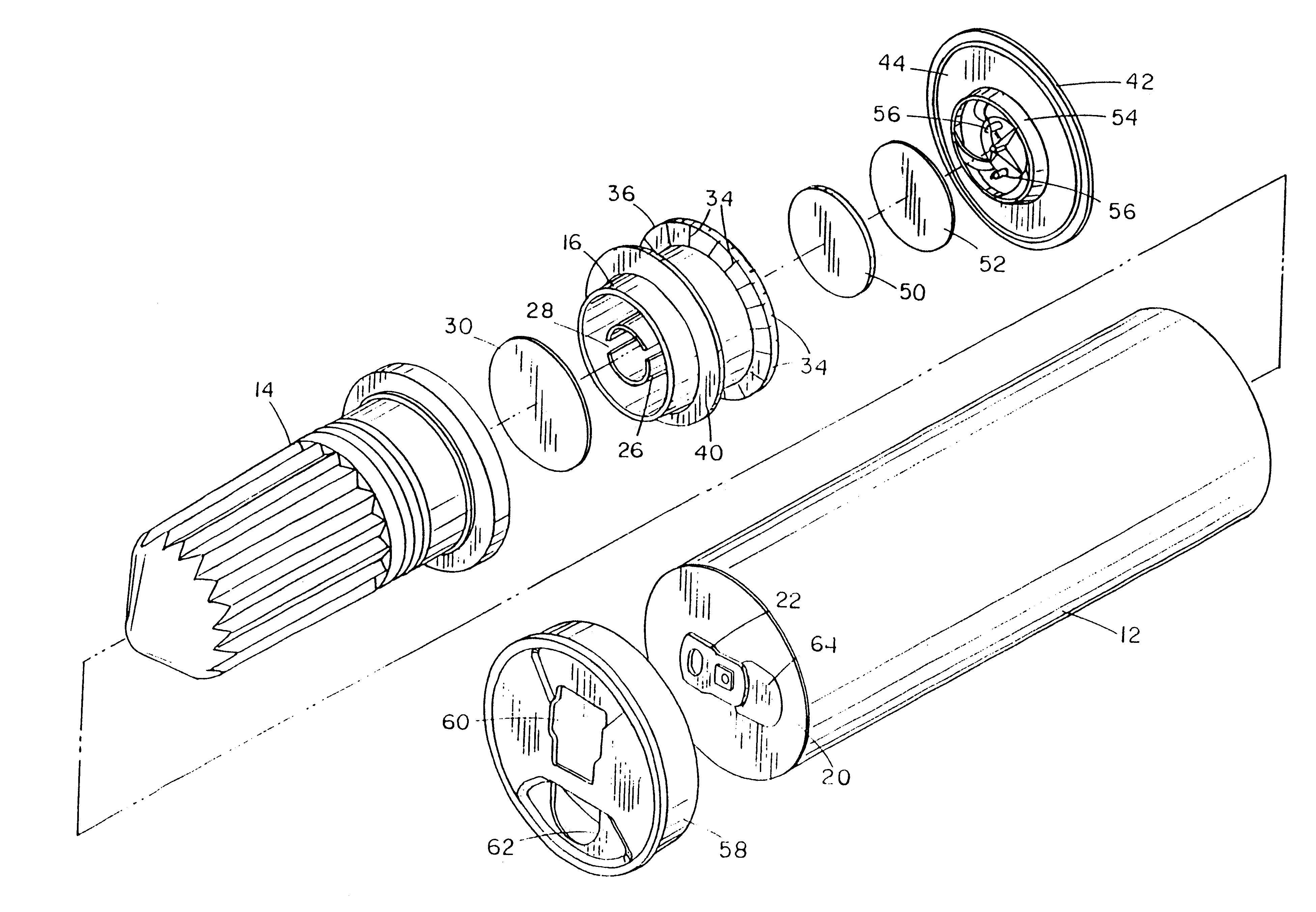
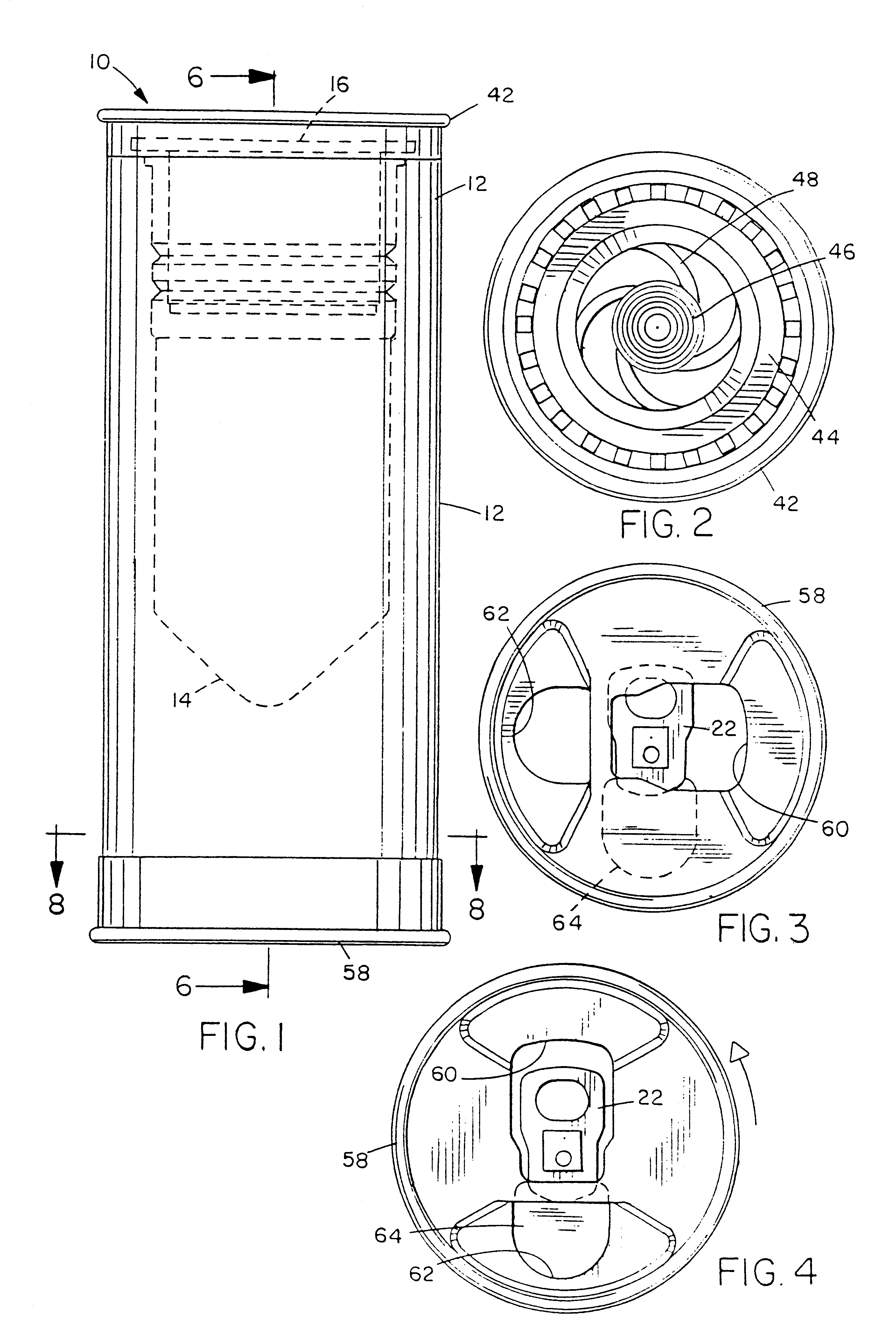
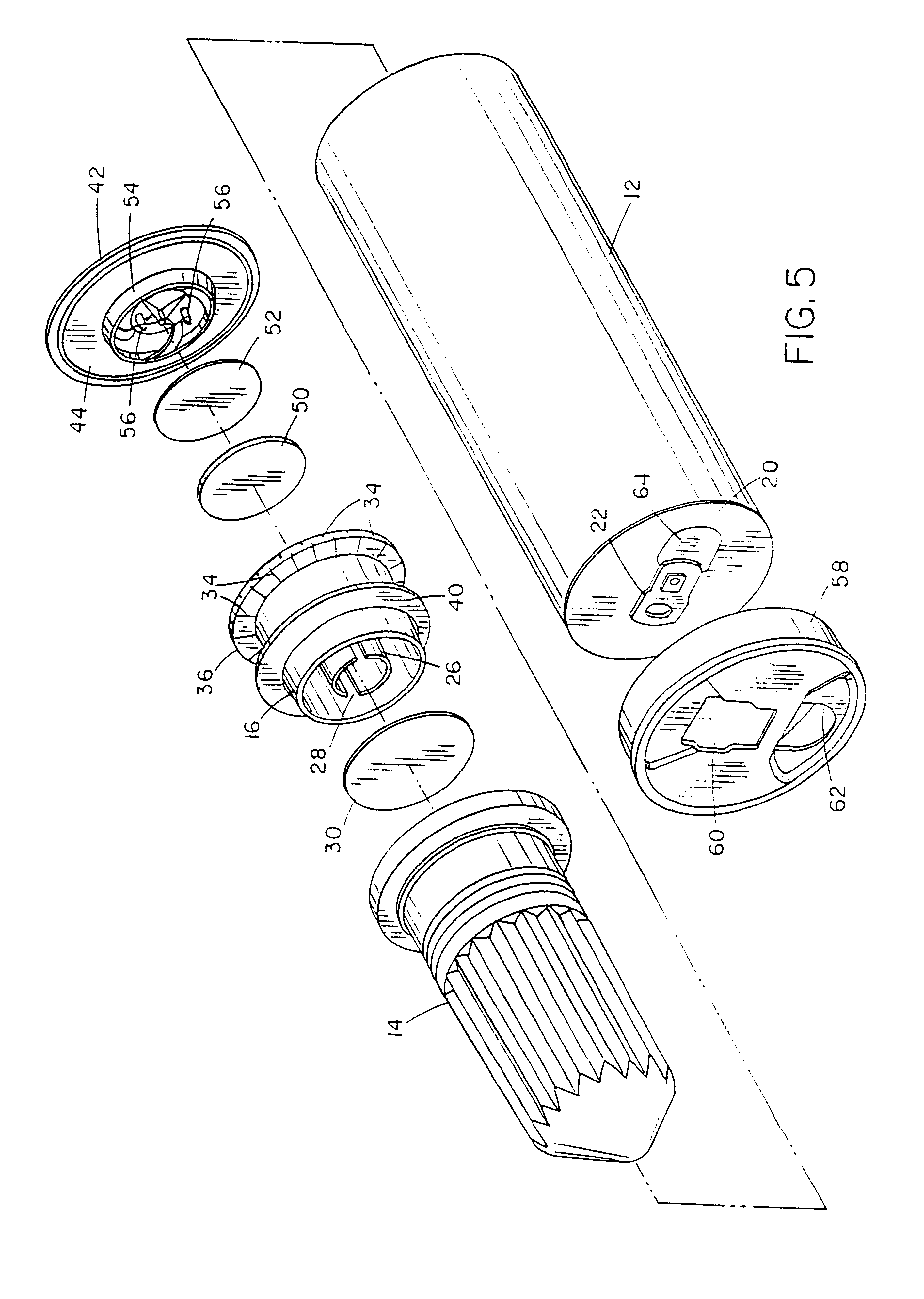
As illustrated in FIGS. 1-8, a container 10 includes a container body 12, a thermic module body 14, and a thermic module cap 16. As best illustrated in FIGS. 5-7, module body 14 has an elongated heat-exchanger portion that extends into container body 16. The interior of this portion defines a reaction chamber in which the reaction occurs that heats (or, in alternative embodiments of the invention, cools) the beverage or other contents 18. The heat-exchanger portion has a corrugated or pleated wall to increase surface area and, as a result, heat transfer. Although in the illustrated embodiment the wall is corrugated or pleated, in other embodiments the wall may have other suitable geometries. Module cap 16 is press-fit in the open end of module body 14. An endcap 20 with a pop-tab closure 22 of the type commonly used in beverage cans is crimped over the other end of container body 12 in the manner of a conventional beverage can.

Module cap 16 is of unitary construction and is made of ...


PUM

PropertyMeasurementUnit
temperatureaaaaaaaaaa
forceaaaaaaaaaa

Abstract

A container having a container body, a thermic module at one end of the body, and a closure at the other end of the body initiates an internal exothermic (or, alternatively, endothermic) chemical reaction to heat its contents when a user actuates the thermic module. A plastic thermic module body is spin-welded to a plastic container body by rotating one relative to and in contact with the other. The container body has multiple layers, including an inner layer such as a so-called oxygen barrier layer that inhibits oxidation and spoilage of the contents, and spin-welding the container body to the module body seals the otherwise-exposed oxygen barrier layer against air or moisture intrusion. The container includes a rotatable cover adhered to the container end over the closure with heat-sensitive adhesive that prevents a user from accessing the contents until a certain temperature is reached. The thermic module further includes a seal between an inner actuator button and an outer actuator button that seals the thermic module reactants against moisture intrusion prior to use, and is punctured when the thermic module is actuated. The thermic module may also include a filter disposed in interfering relation with the thermic module vents, including a portion between the inner and outer actuator buttons, to block egress of any particles of the solid reactant or the reaction product.

Description

1. Field of the InventionThe present invention relates generally to containers that include an internal module that adds heat to or removes heat from the material, such as a food, beverage, medicine, or the like, in the surrounding container.2. Description of the Related ArtContainers may have integral modules for warming materials in the container, such as Japanese sake, coffee, or soup. Examples of such self-heating containers are disclosed in U.S. Pat. Nos. 5,461,867 and 5,626,022, issued to Scudder et al. Such containers typically include an outer can or body, in which the food or beverage is sealed, and an inner can or thermic module that contains two chemical reactants that are stable when separated from one another but, when they mix in response to actuation of the thermic module by a user, produce an exothermic reaction or, alternatively, an endothermic reaction and thereby heat or cool the contents of the container.The heating or cooling module (thermic module) is typically...

Claims


Application Information

Patent Timeline
Patent Type & Authority Patents(United States)
IPC IPC(8): A47J36/28A47J36/24B29C65/06B29C69/00F25D5/02F25D5/00B29C49/04B29C49/22F25D31/00
CPCA47J36/28B29C49/4278B29C65/0672B29C66/54F25D5/02B29C66/5412B29C66/543B29C66/5432B29C66/545Y10T29/4935B29C49/22B29C2791/001B29C2793/00B29K2995/0067F25D31/007F25D2331/803F25D2331/804F25D2331/805Y10T29/49359B29C49/04B29C66/72341B29C66/72343B29C66/8322
Inventor SCUDDER, JAMES A.BERNTSEN, JAMES L.FARNHAM, WILLIAM B.GIBBS, DANDAVERN, ANN T.ROSATO, JERINE J.SLOCUM, MICHAEL S.
Owner AURA LTD
Why Eureka
Try Eureka