Skull mounted electrode lead securing assembly

Inactive Publication Date: 2002-03-12
ELECTRO CORE TECH
View PDF4 Cites 247 Cited by
  • Summary
  • Abstract
  • Description
  • Claims
  • Application Information

AI Technical Summary

Benefits of technology

The upper portion of the lead locking member includes a sliding element which may be manipulated easily between an offset position and an occluding position. These alternate dispositions, and more particularly, the movements between them, are transverse to the axis of the member and the orientation of the electrode. Specifically, the sliding element is a disc which is seated in the upper surface of the lead locking member. The disc is initially offset relative to the hole which is the terminus of the axial channel. The disc slides along a track in the upper surface of the member into a closed position which partially blocks the hole. In this occluding position, the sliding member partially narrows the channel, and if there is an electrode lead extending therethrough, the lead is squeezed by the sliding member and thereby prevented from continued relative motion. The sliding member, or disc, may include at least one small recess into which a tool may be inserted to facilitate the translation between the open and closed positions. The track in which the sliding member translates, may further include a tab, ratchet, catch, or other structural feature by which the surgeon/user may readily recognize if the sliding e

Problems solved by technology

The effects of the field generated by the electrical contacts is highly position dependent, and as a result, movement of the electrode after proper positioning can reduce or eliminate all effectiveness of the treatment.
Unfortunately, the device is very difficult to manipulate in a surgical environment as it requires manual pushing and pulling of small members which are seated within one another, and which have no defined open and closed dispositions which demonstrably indicat

Method used


Image

  • Skull mounted electrode lead securing assembly
  • Skull mounted electrode lead securing assembly
  • Skull mounted electrode lead securing assembly

Examples


Example

While the present invention will be described more fully hereinafter with reference to the accompanying drawings, in which particular embodiments are shown, and with respect to methods of implantation, it is to be understood at the outset that persons skilled in the art may modify the invention herein described while achieving the functions and results of this invention. Accordingly, the descriptions which follow are to be understood as illustrative and exemplary of specific structures, aspects and features within the broad scope of the present invention and not as limiting of such broad scope. Like numbers refer to similar features of like elements throughout.

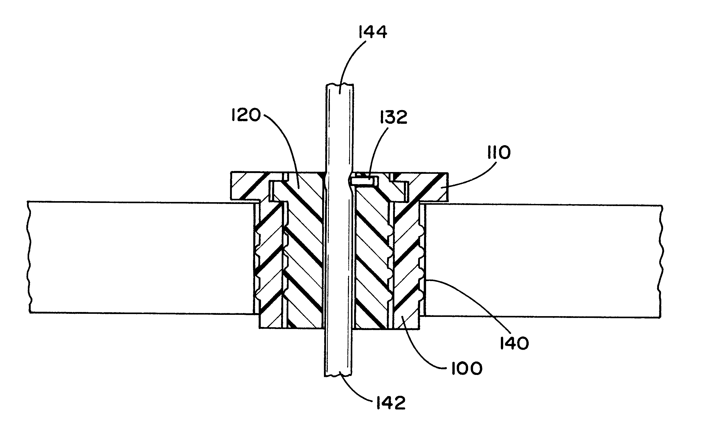
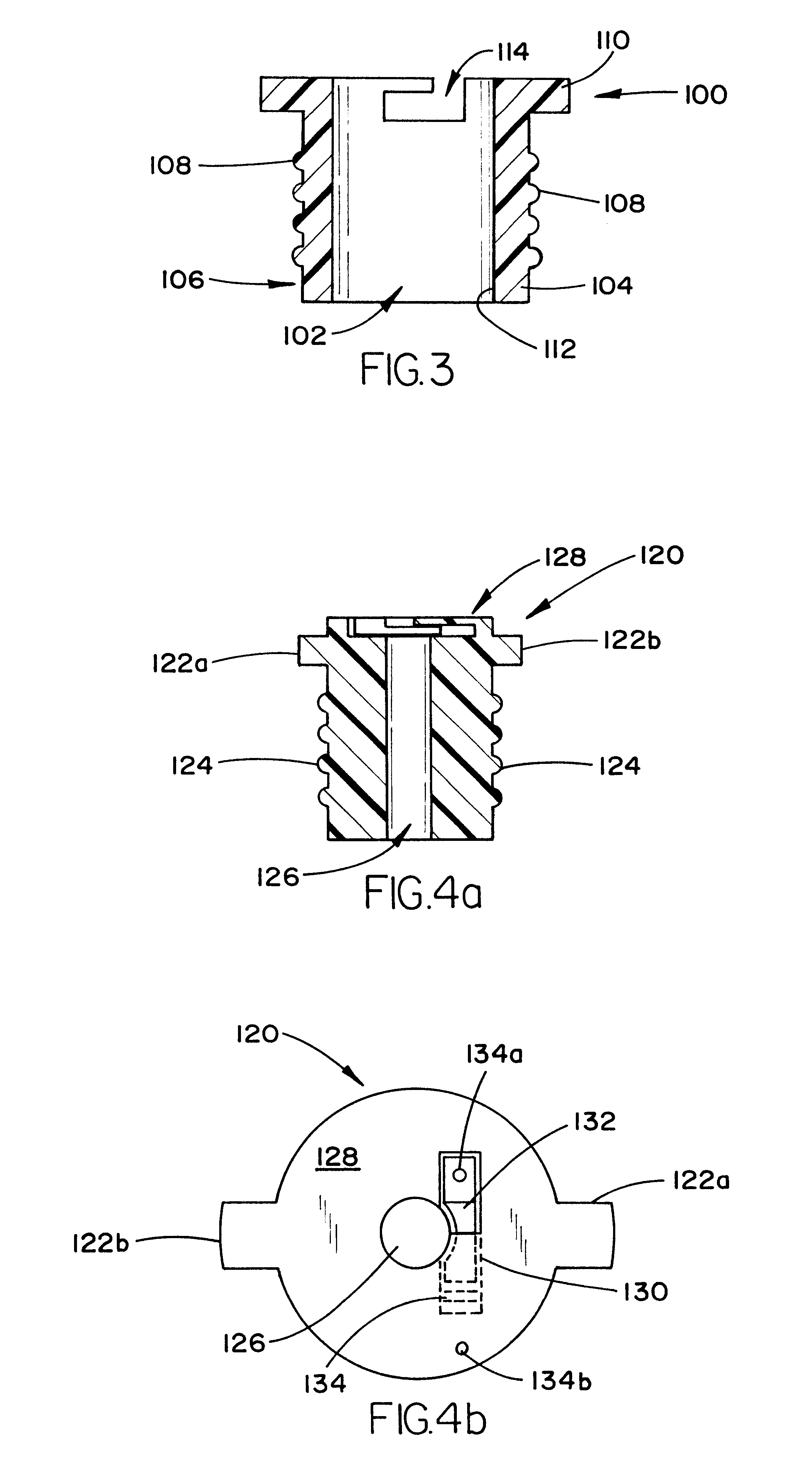
Referring now to FIG. 3, the present invention comprises a cylindrical skull port member 100 which is designed to securely fit within the burr hole formed in a patient's skull,through which the surgeon implants the active tip of the electrode lead. The cylindrical port member 100 includes a central opening 102 and a round side...


PUM


Abstract

An assembly for securing an electrode lead within a burr hole formed in a patient's skull. The assembly is provided for reliably, easily, and reversibly securing an implanted electrode lead such that the active portion of the lead which is inside the brain tissue within the skull is not subject to unwanted translations when the external portion of the lead is manipulated. The securing assembly has two separate components. The first is a bone port which seats within a preformed burr hole in the skull. The bone port is a cylindrical shaped short tube which includes a means for gripping the skull on the external periphery of the cylinder. The central axial hole of the port is designed to receive the second lead-locking portion of the assembly. The external surface of the lead-locking portion and the interior surface of the central axial hole of the port include an easily engageable coupling means, for example a bayonet locking mechanism. The lead-locking portion has a central electrode passage through which the electrode lead may slide freely in an unlocked disposition. The upper section of the lead-locking portion includes a sliding member which may be selectively manipulated between a closed and open position. The sliding member has a lateral edge which, when the member is moved into the closed position, partially occludes the electrode passage such that an electrode is secured by friction in the passage, thus preventing movement of the active implanted portion of the electrode within the skull. The external portion of the electrode, however, can be manipulated freely.

Description

1. Field of the InventionThis invention relates generally to a device used in the interventional treatment of neurological disorders, and more particularly to a novel electrode lead securing member which mounts to a burr hole in the patient's skull and prevents undesirable translation of the implanted lead as the external portion of the lead is manipulated during surgery.2. Description of the Prior ArtThe use of electrical stimulation of the brain for the purposes of alleviating pain and the treatment of other neurological afflictions has been utilized for a number of years, and in many instances has become the standard of care. The technique comprises the implantation of a long flexible electrical lead through a burr hole in the patient's skull, and into electrical contact with the pathological section of the patient's brain. The flexible lead comprises a plurality of long hetically wound wires encased in a elastomeric sheath. The distal end of the wire leads include electrical con...

Claims


Application Information

Patent Timeline
IPC IPC(8): A61N1/05
CPCA61N1/0534A61N1/0558A61N1/0539
Inventor ERRICO, JOSEPH P.ZONENSHAYN, MARTIN
Owner ELECTRO CORE TECH
Why Eureka
Try Eureka