Termite bait cover

a termite and cover technology, applied in the field of termite bait cover, can solve the problems of time-consuming removal methods and drive termites away, and achieve the effect of enhancing the effectiveness of the termite baiting system and reducing or preventing moisture and light intrusion

Inactive Publication Date: 2002-03-19
CITY OF NEW ORLEANS +1
View PDF7 Cites 18 Cited by
  • Summary
  • Abstract
  • Description
  • Claims
  • Application Information

AI Technical Summary

Benefits of technology

It is an object of this invention to allow a termite bait station to be evaluated for presence or absence of termites and termite activity without removing the bait cover.
Apertures in the bottom plate or top plate of the termite bait cover allow termite activity to be detected by conventional and future technologies. Preferably, the top plate has apertures, the apertures tapering from the bottom surface of the top

Problems solved by technology

Removal of the termite bait cover disturbs the feeding process of termites and tends to drive the termites away from

Method used


Image

  • Termite bait cover
  • Termite bait cover
  • Termite bait cover

Examples


example 2

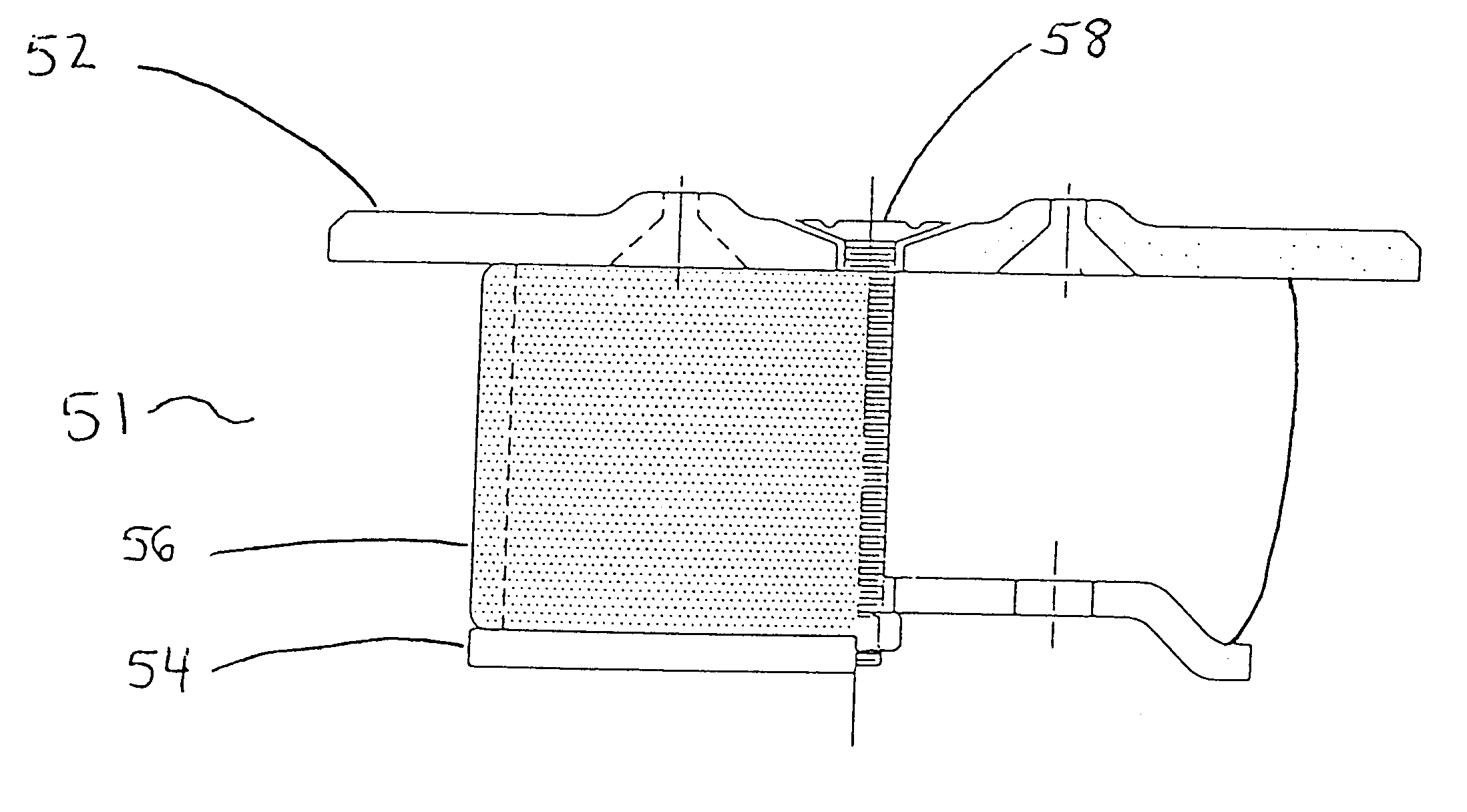
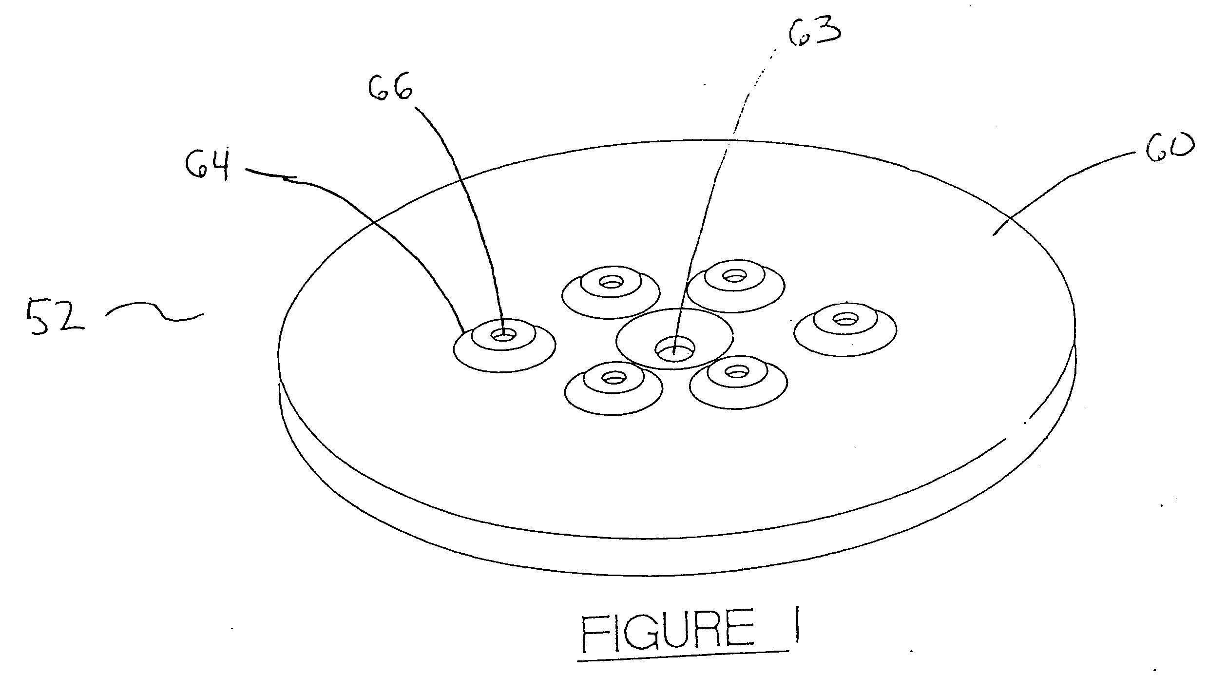
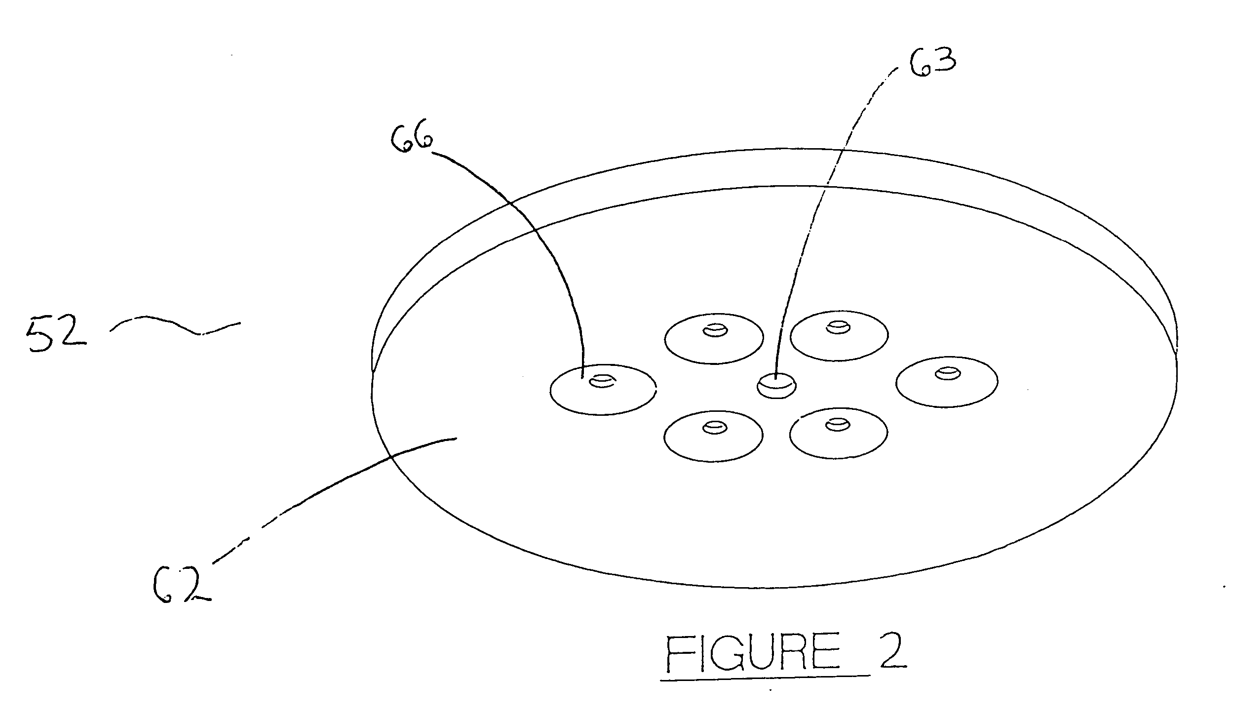
Termite cover assembly 51, with top plate 60 preferably made of metal, is placed into an opening in a sidewalk, with plug 80 made of rubber placed in each aperture 66. When monitoring the termite bait station one or more plugs 80 are removed from dimples 66, and fiber-optic visual monitoring equipment is inserted through apertures 66 in top plate 52 and apertures 74 in bottom plate 54. When inspection is complete, plugs 80 are replaced in apertures 66.

example 3

Termite bait cover assembly 51 is placed into a termite bait station opening. The termite bait station contains an electronic device that monitors termite activity. In response to a signal from outside the termite bait station, the electronic device transmits a signal indicating whether the presence of termites has been detected. An embodiment of the present invention having additional apertures in the top plate, bottom plate, top disc and / or bottom cup allows successful transmission detection of the electronic signals at a lower power level and greater range than would be possible with the invention disclosed in U.S. Pat. No. 5,927,000.


PUM


Abstract

A system for detecting and monitoring termite infestation includes cover assembly having top and bottom plates having axially aligned apertures and linked by a threaded bolt, and bore gasket disposed between the plates. Bottom plates have additional apertures. Top plates have protruding dimples with nonslip surface and coating, tapered apertures therethrough, and plugs or, alternatively, an essentially flat top surface and areas of reduced thickness. An alternative cover assembly includes a top having a top disc portion with an axially aligned aperture therethrough and protruding dimples with tapered apertures and a cylinder portion, axially disposed downward therefrom and having retaining ridges encircling its exterior surface and rows of teeth axially disposed upon its inner surface; and a bottom cup in the shape of a tapered cylinder having a bottom covering, the bottom cup having an axially aligned aperture therethrough, additional apertures, and teeth axially disposed on the exterior surface thereof.

Description

BACKGROUND OF THE INVENTION: FIELD OF THE INVENTION AND DESCRIPTION OF RELATED ARTThe present invention relates to an improvement of the Tamper Resistant Bait Cover (U.S. Pat. No. 5,927,000 to Edgar S. Bordes, Jr.). Accordingly, applicant incorporates by reference the section of U.S. Pat. No. 5,927,000 entitled "Background of the Invention," including the description therein of the field of the invention, the related art, and the objects of the invention. Applicant also incorporates the section entitled "Summary of the Invention" and the drawings of U.S. Pat. No. 5,927,000.Additional art related to the field of this invention includes U.S. Pat. No. 6,079,150 to Setikeas et al., which describes an insect-control system and method in the same general field as applicant's U.S. Pat. No. 5,927,000.The termite bait cover assembly disclosed in Pat. No. 5,927,000 requires the removal of the termite bait cover to detect the presence or absence of the target insect. Removal of the termite bai...

Claims


Application Information

Patent Timeline
IPC IPC(8): A01M1/02A01M1/20
CPCA01M1/026A01M1/2011A01M2200/011
Inventor BORDES, JR., EDGAR S.
Owner CITY OF NEW ORLEANS
Why Eureka
Try Eureka