
Method and apparatus for determining a processor failure in a multiprocessor computer

a multi-processor computer and processor technology, applied in the field of computer systems, can solve the problems of failure of the entire network, failure of one of the multiple processors, and limited size and cost of high-speed memory

Inactive Publication Date: 2002-03-19
HEWLETT-PACKARD ENTERPRISE DEV LP
View PDF18 Cites 57 Cited by
  • Summary
  • Abstract
  • Description
  • Claims
  • Application Information

AI Technical Summary

Problems solved by technology

However, due to the extremely limited computing capabilities of these early microprocessors and the limited size and costliness of high speed memory, these early personal computers truly were nothing but stand alone personal computing devices.
In other words, because the servers typically provide applications, data, and communications among the various workstations, the failure of one server could cause the entire network to fail.
In a multiprocessor computer such as those typically used as servers, one problem that may occur involves the failure of one of the multiple processors.
While this scheme facilitates the detection of a failed secondary microprocessor, it does not address a situation where the primary microprocessor fails.
In such a situation, the primary microprocessor would be unable to activate the secondary processors, leaving the entire server incapacitated even though one or more secondary processors may remain fully operational.
Clearly, if a processor fails and causes the server to be shut down, the network will at least lose the availability of that server even though the server may still contain several operable processors, and, of course, the removal of the server may cause the entire network to go down.
However, if the results do not match, then one of the processors is assumed to have failed.
However, in a dual processor system, such a method merely provides an indication that one of the two processors has failed, without providing an indication of which particular processor has failed.
Without being able to determine which processor has failed, the computer system cannot discontinue use of the failed processor and it cannot identify the failed processor for subsequent replacement.

Method used


Image

  • Method and apparatus for determining a processor failure in a multiprocessor computer
  • Method and apparatus for determining a processor failure in a multiprocessor computer
  • Method and apparatus for determining a processor failure in a multiprocessor computer

Examples


Embodiment Construction

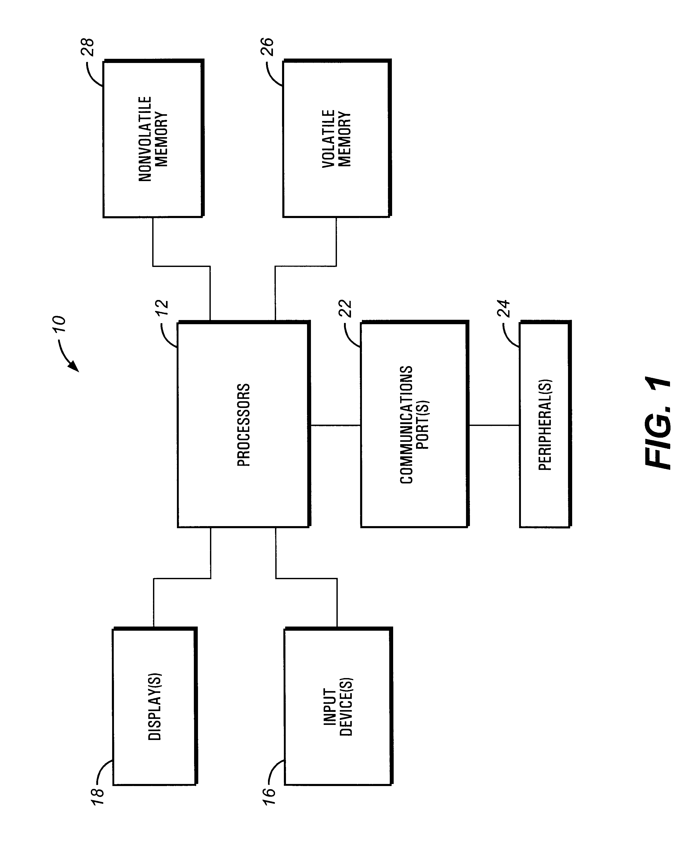
Turning now to the drawings, and referring initially to FIG. 1, a block diagram depicting a multiprocessor computer system, generally designated by the reference numeral 10, is illustrated. In this embodiment of the system 10, multiple processors 12, such as microprocessors, control many of the functions of the system 10. In one particular embodiment, the processors 12 may be, for example, Pentium Pro or Slot-2 processors available from Intel Corporation.

Various other devices may be coupled to the processors 12, depending upon the functions that the system 10 performs. For instance, the system 10 may include various input devices. The input devices may include user interfaces such as a keyboard, a mouse, and / or a voice recognition system, for instance. The system 10 may also include a display 18. The display 18 may include a CRT, a flat panel display, LEDs, and / or an audio system, for instance.

A communications port 22, such as a network interface card for example, may also be couple...


PUM


Abstract

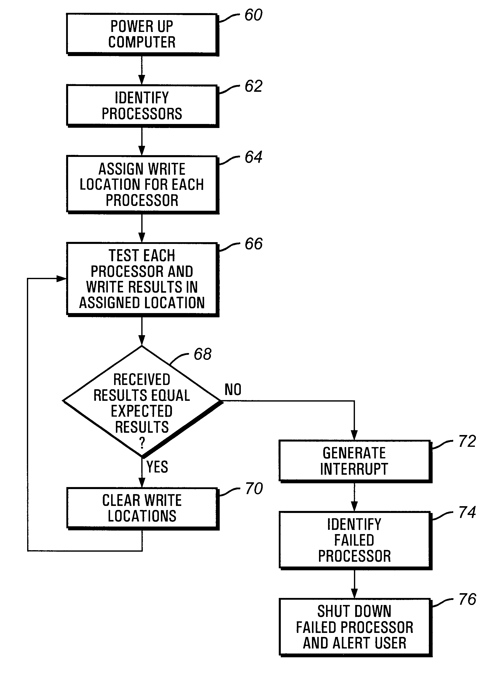
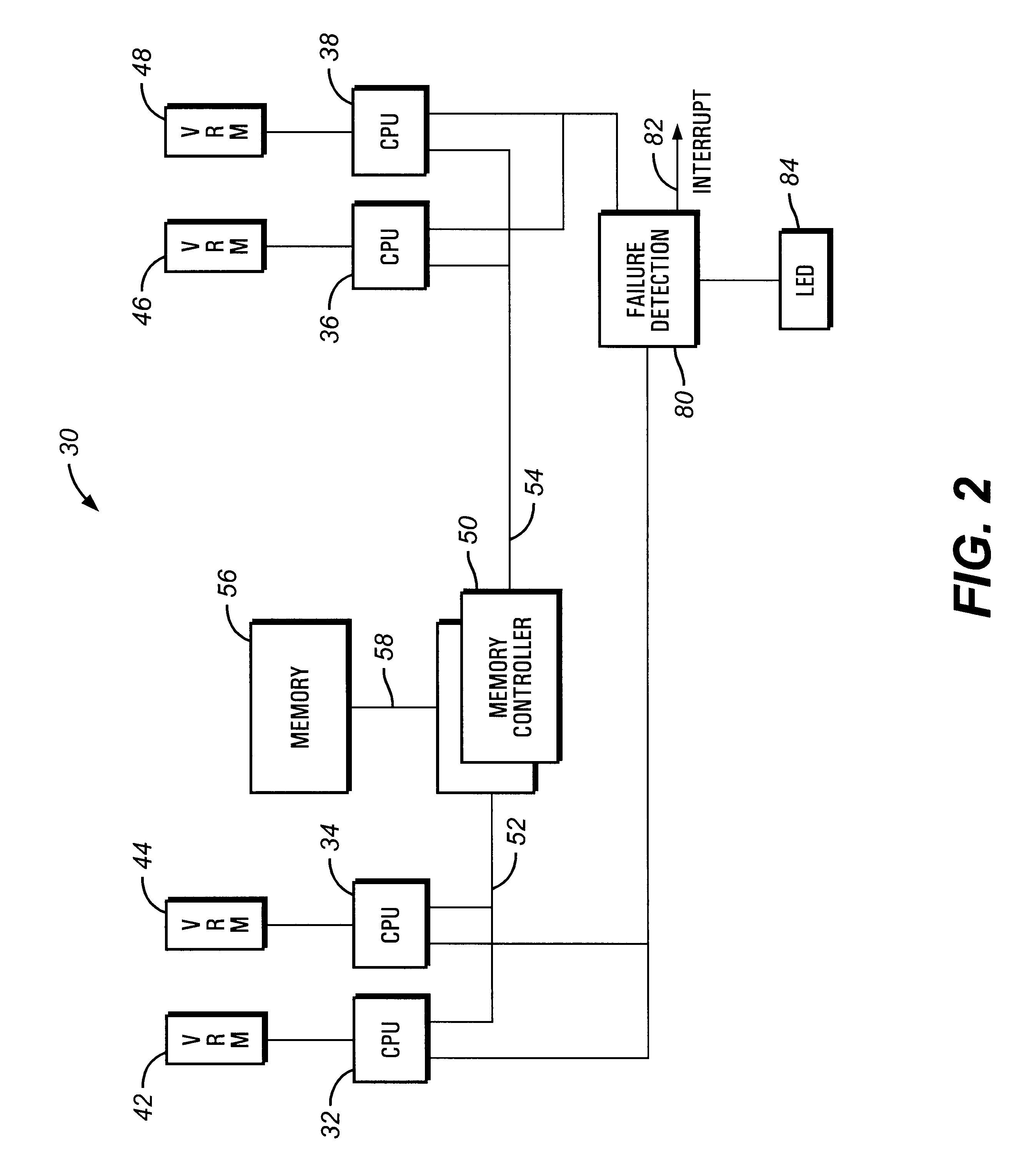
A multiprocessor computer includes a fault detection scheme which detects and identifies the failure of one of the processors. Each processor is assigned a write location, which may be a unique register. During normal computer operation, each processor intermittently performs a test and stores the results of the test in the assigned write location. The stored results are compared to expected results, and an error signal is generated if the stored results differ from the expected results to indicate that one of the processors has failed.

Description

1. Field of the InventionThe present invention relates generally to computer systems and, more particularly, to methods and apparatus for determining when a processor has failed.2. Description of the Related ArtAbout two decades ago, a relatively compact and basic computing device, which would come to be known as the personal computer or PC, was being developed. Like all personal computers since, these early personal computers utilized microprocessors coupled to various types of memory devices. However, due to the extremely limited computing capabilities of these early microprocessors and the limited size and costliness of high speed memory, these early personal computers truly were nothing but stand alone personal computing devices.In the intervening years, microprocessors, memory devices, software, and many other portions of a computing system have seen rapid improvements in speed, capacity, complexity, and performance. By way of example, the latest generation microprocessors from...

Claims


Application Information

Patent Timeline
Patent Type & Authority Patents(United States)
IPC IPC(8): G06F11/20G06F11/267
CPCG06F11/202G06F11/2236G06F11/2046G06F11/2035
Inventor JANSEN, KENNETH A.OLARIG, SOMPONG P.JENNE, JOHN E.
Owner HEWLETT-PACKARD ENTERPRISE DEV LP
Learn More