Pulse wave diagnosing device

a technology of pulse wave and diagnostic device, which is applied in the direction of instruments, catheters, angiography, etc., can solve the problems of difficult to teach this technique, difficult to get an accurate pulse type, and difficulty in obtaining exercise intensity based on subjective evaluation

Inactive Publication Date: 2002-03-26
SEIKO EPSON CORP
View PDF33 Cites 386 Cited by
  • Summary
  • Abstract
  • Description
  • Claims
  • Application Information

AI Technical Summary

Problems solved by technology

However, since the pulse wave is used to diagnose the body's state based on very subtle touch sensations felt through the fingers of the examiner, it can be difficult to teach this technique.
Moreover, if body motion is present, then it can be particularly difficult to get an accurate pulse type due to fluctuations in bloo...

Method used


Image

  • Pulse wave diagnosing device
  • Pulse wave diagnosing device
  • Pulse wave diagnosing device

Examples


second embodiment

The second embodiment employed a design in which the stride was corrected according to the pitch during running. However, a situation may be considered in which the stride varies not only with the pitch during running, but also in accordance with the pulse.

A design is also acceptable employing a table similar to table 2135 in which the relationship between pulse rate and the stride correction coefficient is stored in advance.

When both pitch and pulse rate are taken into consideration when correcting the stride, then a design is also acceptable which employs both pitch and pulse rate as parameters when recording the stride correction coefficient, to generate a two-dimensional table. In this case, as shown by the broken line (1) in FIG. 58, the pulse rate obtained by FFT processor 2103 is supplied as a parameter for two dimensional table 2135.

2-5: Modifications for Chapter 2

The exercise performed by the subject in the first and second embodiments was running, however, the present inve...

embodiment 1

4-2-2: Embodiment 1

The first through seventh embodiments relate to a cardiac function diagnosing device employing a cardiac output detecting device. The eighth through fourteenth embodiments relate to a cardiac function diagnosing device employing a stroke-volume-per-beat detecting device.

4-2-2-1: Structure of Embodiment 1

The structure of a cardiac function diagnosing device employing the cardiac output detecting device according to the first embodiment of the present invention will now be explained with reference to the accompanying figures.

4-2-2-1-1: External Structure of Embodiment 1

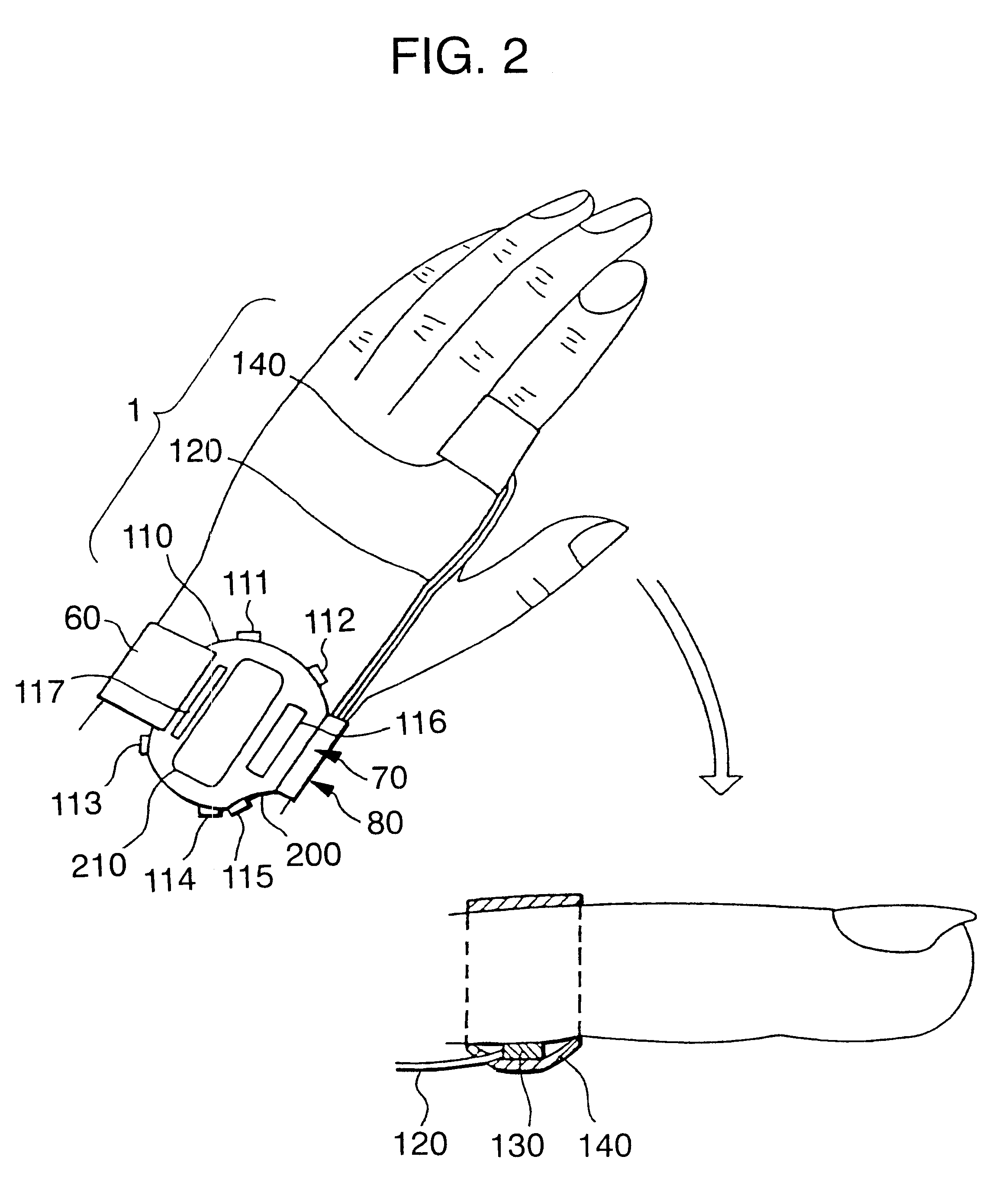
The external structure of cardiac function diagnosing device 42 in this example is the same as that of pulse wave diagnosing device1 explained in Chapter 1 (see FIG. 2). Namely, roughly speaking, cardiac function diagnosing device 42 is formed of a device main body 110 in the form of a wrist watch, a cable 120 which connects to device main body 110, and pulse wave detection sensor unit 130 which is pr...

embodiment 2

1. Structure of Embodiment 2

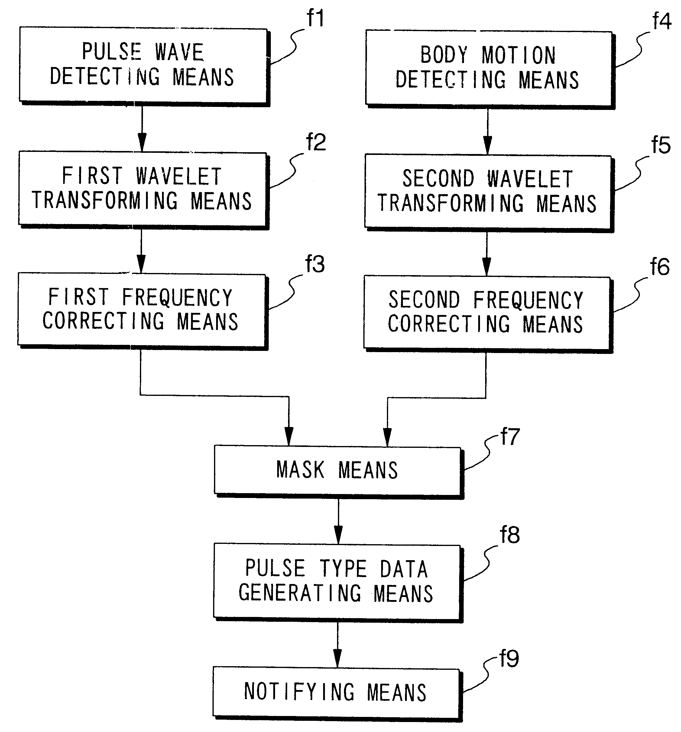
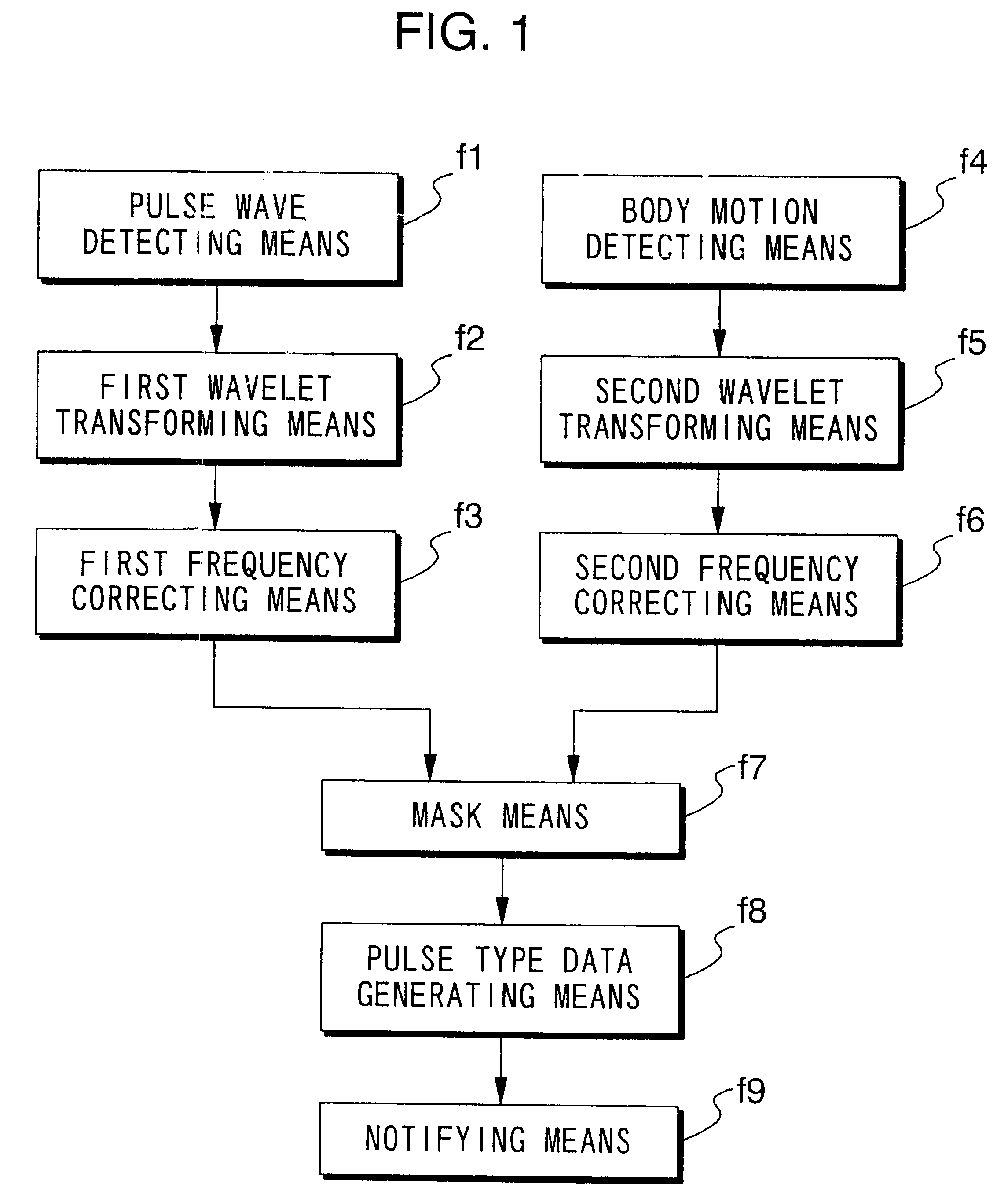
FIG. 90 is a block diagram of a cardiac function diagnosing device 42 according to the second embodiment. As in the first embodiment, in the second embodiment, the body motion component MHt is detected using acceleration sensor 130' and waveform processor 410. However, this embodiment differs from the first embodiment in that body motion component removal and heart rate and ejection duration detection are carried out using wavelet transformation. The external structure of the second embodiment is the same as that of the first embodiment shown in FIG. 2.

4-2-3-1-1: First and Second Wavelet Transformers, and First and Second Frequency Correctors

In FIG. 90, a first wavelet transformer 420 performs conventional wavelet transformation on pulse waveform MH output from pulse wave detection sensor unit 130, to generate analyzed pulse wave data MKD. Second wavelet transformer 422 performs conventional wavelet transformation on body motion waveform MHt output from a...


PUM


Abstract

When pulse waveform MH is detected by pulse wave detection sensor unit 130, wavelet transformer 10 performs wavelet transformation on pulse waveform MH and generates analyzed pulse wave data MKD. This analyzed pulse wave data MKD consists of a time region in which one heartbeat is divided into eighths, and the frequency region of 0-4 Hz which has been divided into eighths. Frequency corrector 11 generates corrected pulse wave data MKD' by performing frequency correction on analyzed pulse wave data MKD. Pulse type data generator 12 compares corrected pulse wave data MKD' over each frequency-time region, and generates pulse type data ZD indicating the type of pulse. Display 13 displays the pulse type for pulse waveform MH based on pulse type data ZD.

Description

1. Technical FieldThe present invention relates to a method and device for extracting information related to the body's state from the pulse wave, and measuring or diagnosing the body's state based on this extracted information.2. Background of the InventionBlood pressure, heart rate and the like are typical measurements employed when diagnosing the condition of the circulatory system in the human body. Accordingly, systolic and diastolic blood pressure values and pulse rates measured in the body are of great importance as a type of information for understanding the state of the circulatory system and, in a greater sense, the state of the body. Since these indices are obtained by measuring the pulse over a fixed period of time, they serve as representative values for the period of measurement.As research on pulse waves has progressed, it has become clear that a variety of physiological states which cannot be gleaned from blood pressure values and the pulse rate alone, can be obtaine...

Claims


Application Information

Patent Timeline
IPC IPC(8): G06F17/00
CPCA61B5/02028A61B5/0205A61B5/021A61B5/4854A61B5/6814A61B5/721A61B5/726A61B5/0295A61B5/024A61B5/029A61B5/7239A61B5/7257A61B5/02108
Inventor AMANO, KAZUHIKOUEBABA, KAZUOISHIYAMA, HITOSHI
Owner SEIKO EPSON CORP
Why Eureka
Try Eureka