Automatic gain control

a gain control and automatic technology, applied in the field of automatic gain control, can solve the problems of deafness of the called party, difficulty in hearing the calling party,

Inactive Publication Date: 2002-03-26
NOKIA TECHNOLOGLES OY
View PDF17 Cites 14 Cited by
  • Summary
  • Abstract
  • Description
  • Claims
  • Application Information

AI Technical Summary

Problems solved by technology

Unfortunately, if a user, say the calling party, wants to lower the volume of their voice, for example when privacy is required from people nearby or the user wants to minimise the disturbance to other people, the called party may have difficulty in hearing the calli...

Method used


Image

  • Automatic gain control
  • Automatic gain control
  • Automatic gain control

Examples


Embodiment Construction

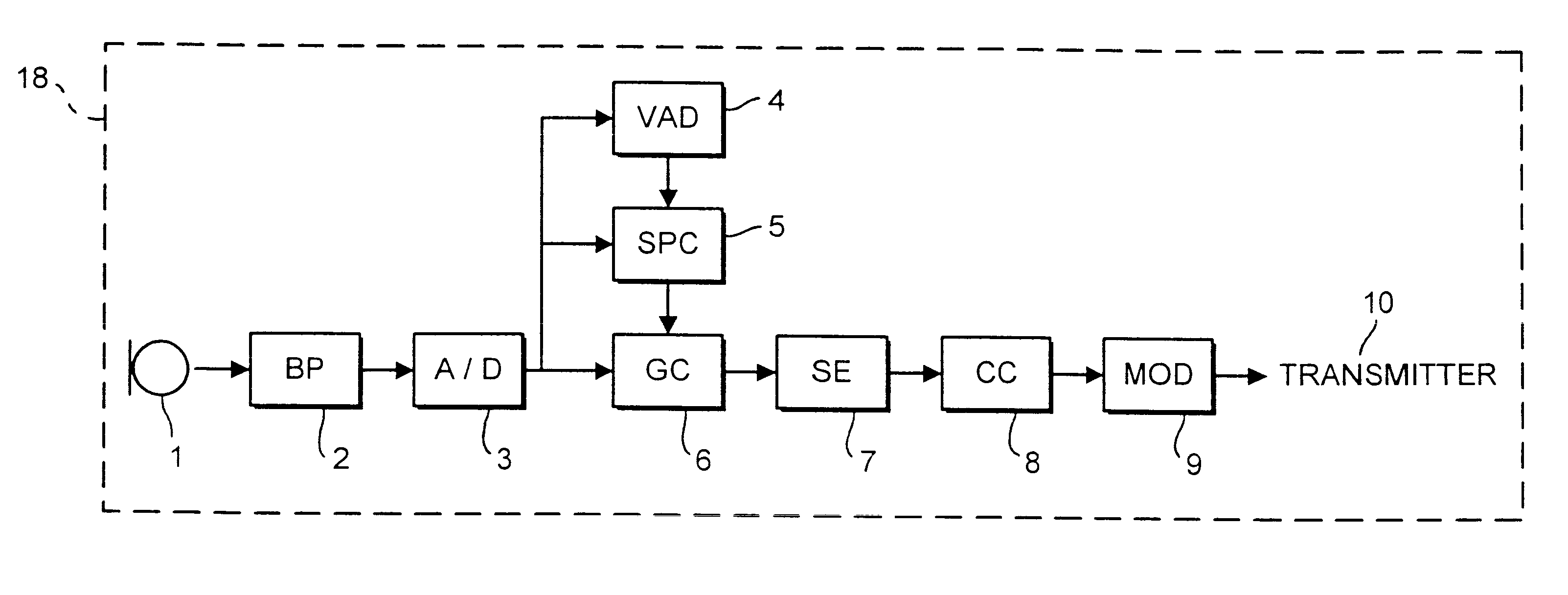
This invention is applicable to both digital and analogue telephones in a wired or wireless telecommunications system. This specific embodiment, however, is directed to automatic gain control circuitry in a digital radio telephone.

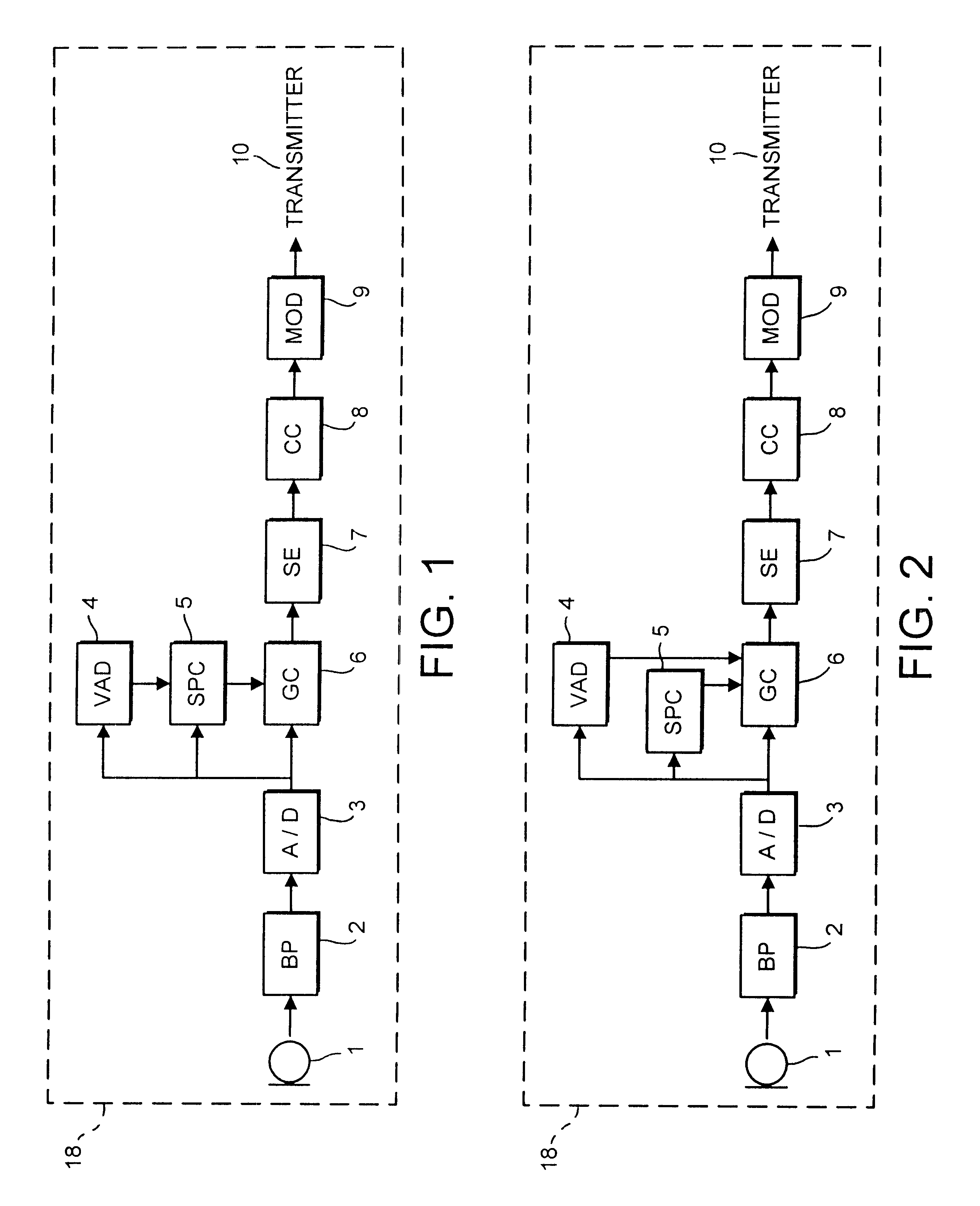
FIG. 1 illustrates an example of an automatic gain control circuit in the transmitting section of a mobile phone 18. A microphone 1 is coupled to a bandpass filter 2 which is coupled to an analogue to digital converter 3. The analogue to digital converter 3 is coupled to an activity detector 4 which will typically be a voice or speech activity detector, a signal power calculator 5 and a gain controller 6. The speech activity detector 4 is coupled to the signal power calculator 5 which is coupled to the gain controller 6. The gain controller 6 is coupled to a speech encoder 7 which is coupled to a channel coder 8. The channel coder 8 is coupled to a modulator 9 which is coupled to a transmitter 10. The automatic gain control circuit comprises the gain contr...


PUM


Abstract

A gain control circuit for a telephone, the circuit comprising a signal strength calculator for calculating the strength of a signal; a gain controller adapted to modify the strength of the signal in accordance with a predetermined criterion based on the strength of the signal calculated by the signal strength calculator.

Description

This invention relates to a gain control circuit in particular, but not exclusively, for a telephone.DESCRIPTION OF THE PRIOR ARTWhen a user of a telephone speaks into the microphone, the microphone converts the sound into either an analogue or digital electric signal which is then amplified and processed before the signal is transmitted onto the telecommunications network, which may be a wired or wireless system.Typically the amplification of the voice signal is fixed and set at a level suitable for volumes used in normal conversation. Unfortunately, if a user, say the calling party, wants to lower the volume of their voice, for example when privacy is required from people nearby or the user wants to minimise the disturbance to other people, the called party may have difficulty in hearing the calling party. One solution to this problem has been to incorporate into the phone a `whisper` mode which is selected by the user when required. When in this mode the gain of the voice signal ...

Claims


Application Information

Patent Timeline
IPC IPC(8): H03G3/30H04M1/00H04B3/06H04M1/58
CPCH03G3/3089
Inventor HOROS, JACEK ANDRZEJ
Owner NOKIA TECHNOLOGLES OY
Why Eureka
Try Eureka