Passive collimating tubular skylight

a tubular skylight and collimator technology, applied in skylights/domes, optical elements, instruments, etc., can solve the problems of not being able to achieve macduff's arrangement, not being able to achieve foster's refractive collimator, and not being able to achieve the effect of a tubular skylight or a tubular skyligh

Inactive Publication Date: 2002-04-02
ENTECH INC
View PDF23 Cites 101 Cited by
  • Summary
  • Abstract
  • Description
  • Claims
  • Application Information

AI Technical Summary

Benefits of technology

Other objects and advantages of the invention include improved passive tubular skylights, said improved skylights providing better all-day illumination in the desired working area beneath the skylight. Still further objects and advantages of the invention include improved passive tubular skylights, said improved skylights providing better throughput optical efficiency. Still further objects and advantages of the invention include improved passive tubular skylights, said improved skylights providing better light distribution within the interior space of the building.

Problems solved by technology

However, neither the prior art tubular skylight nor the conventional skylight is very effective in providing good illumination, throughout the entire day, in the room area just beneath the skylight, because of the highly variable angles of incidence of the rays of solar radiation intercepting the energy-collecting aperture.
As will be shown below, MacDuff's arrangement is not feasible when the second law of thermodynamics is fully considered.
As will be shown below, Foster's refractive collimator is not feasible when the second law of thermodynamics is fully considered.
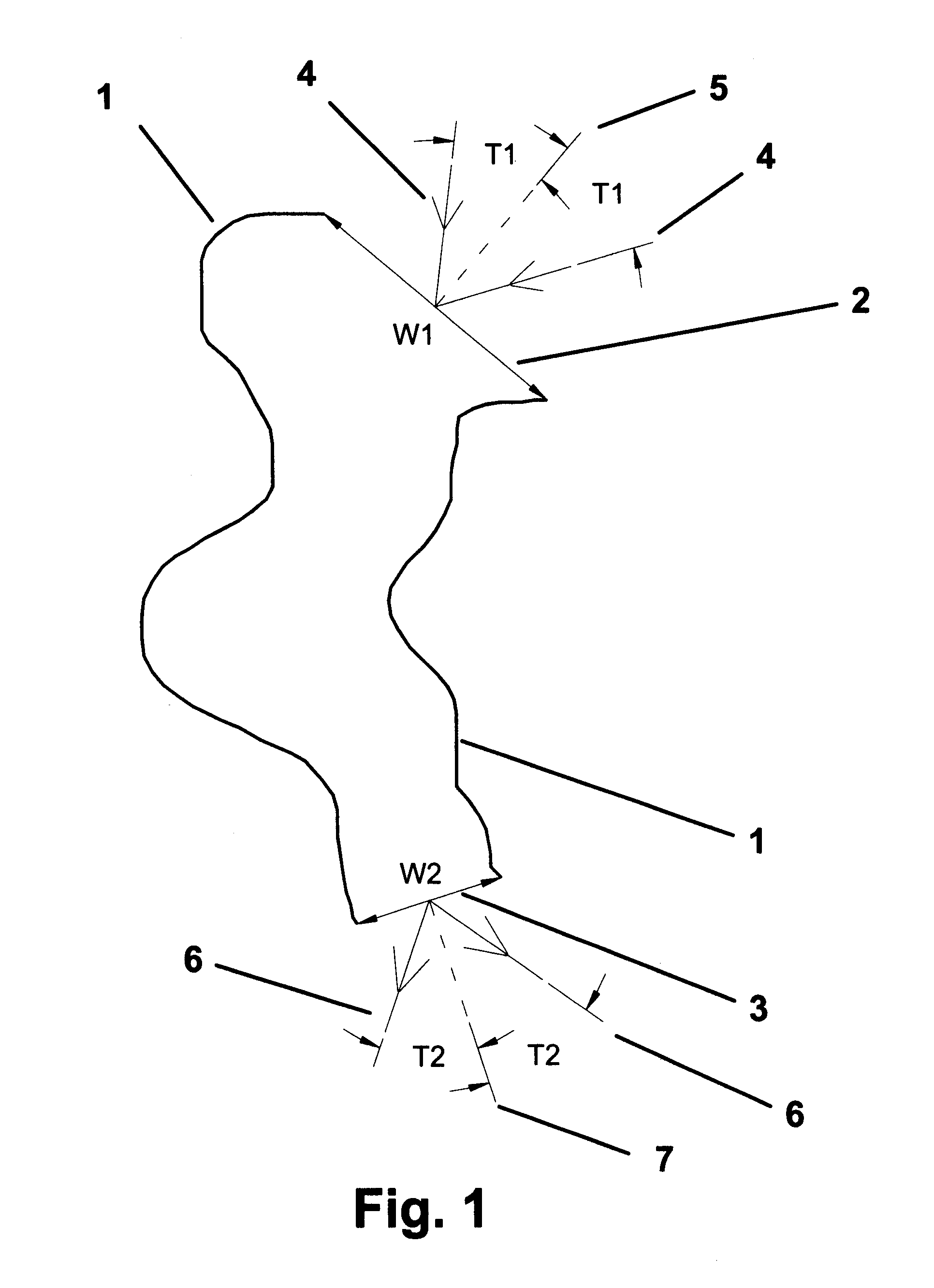
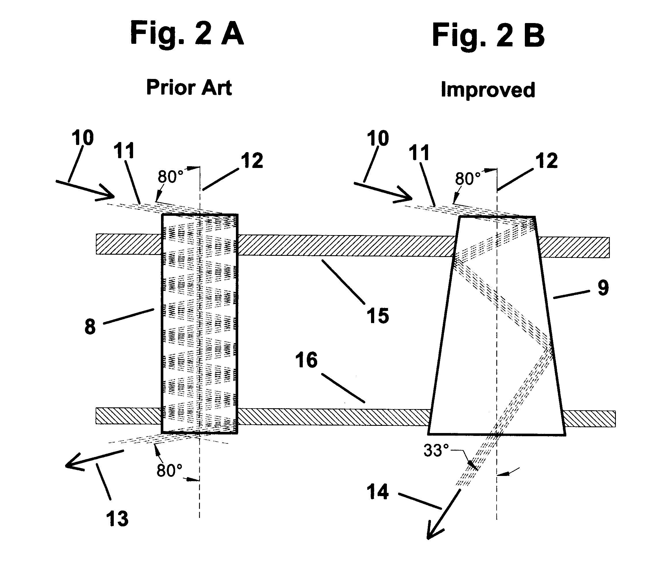
As will be shown below, such a reduction in light tube width or diameter from the energy-capturing aperture to the energy-delivering luminaire is counterproductive in terms of light collimation.
However, none of the prior devices disclosed in the art include practical means for collimating the collected sunlight so that it may be delivered to the desired location within the room below throughout the entire day.
Indeed, prior passive tubular skylights which recognize the need for such collimation, including those illustrated in patents issued to MacDuff, Foster, and Martinet, present configurations which cannot provide such collimation because of a fundamental physical principle, as set forth in the second law of thermodynamics.
The other prior skylights do not recognize or address the need for such collimation.
Therefore, the collimation means discussed by MacDuff, Foster, and Martinet cannot be realized in a physical skylight.
However, this rationale in no way describes the configuration of the skylight between the energy-collecting and energy-delivering apertures to effect such improved collimation.

Method used


Image

  • Passive collimating tubular skylight
  • Passive collimating tubular skylight
  • Passive collimating tubular skylight

Examples


Embodiment Construction

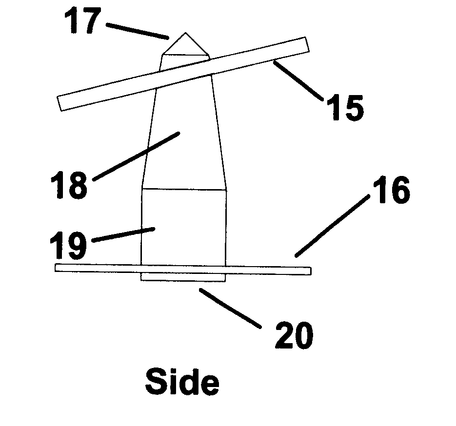
prototype, similar in configuration to the embodiment shown in FIGS. 5A-5B, save the absence of extension 21, was tested. For the test prototype, the energy-collection aperture 22 was sized at 12 inches (30 cm) square, and was tilted to the south by 45 degrees, a reasonable angle for the location of the test in Keller, Tex., USA, where the local latitude is 33 degrees. The collimating tube 18 was 36 inches (91 cm) long, with a 12 inch long extension section 19. A translucent white diffuser, known as "White Cracked Ice," was used on the energy-delivering aperture 20, which was sized at 22 inches (56 cm) square. For comparison, a commercially available tubular skylight, of the type taught by DeBlock in U.S. Pat. No. 5,655,339, was purchased and installed next to the prototype. The commercial unit had a clear plastic dome, with prismatic back reflector, on top of a 10 inch (25 cm) diameter tube, whose inner surface used Alcoa EVERBRITE 95.RTM. reflector material. The only modification ...


PUM


Abstract

A passive collimating tubular skylight consisting of a radiant energy-collecting aperture, a radiant energy-delivering aperture, and a radiant energy passageway between these two apertures, the passageway having a specularly reflective interior surface and a configuration to improve the collimation of the radiant energy passing therethrough. The skylight can be configured with the radiant energy-collecting aperture located above the roof of a building, oriented to collect sunlight; and equipped with a sealed weatherproof glazing, with the radiant energy-delivering aperture, or luminaire, located at ceiling level within the building, and equipped with a diffusing glazing; and with the reflective tubular light passageway constructed with a larger cross sectional area near the radiant energy-delivering aperture than near the radiant energy-collecting aperture. In complete accord with the second law of thermodynamics, and as proven by experimental results, the new passive collimating tubular skylight provides significant advantages over the prior art, including better solar energy collection, higher throughput optical efficiency, improved radiant energy collimation, enhanced interior illumination levels, and more precise positional control of the interior illumination.

Description

BACKGROUND--FIELD OF INVENTIONThe present invention relates generally to skylights, and more particularly to tubular skylights, which use an enclosed hollow passageway, or light tunnel, to convey the sunlight from the energy-collecting aperture (or skylight) on the roof, to the energy-delivering aperture (or luminaire) inside the building. The present invention further relates to a passive skylight, with no moving parts, as opposed to an active skylight, with sun-tracking reflectors or lenses.BACKGROUND--DESCRIPTION OF PRIOR ARTMass-produced passive tubular skylights are becoming increasingly popular due to their relatively low cost, compared to conventional skylights, which use expensive frame-and-plasterboard construction of the light passageway from the energy-collecting aperture to the interior of the room. However, neither the prior art tubular skylight nor the conventional skylight is very effective in providing good illumination, throughout the entire day, in the room area ju...

Claims


Application Information

Patent Timeline
Patent Type & Authority Patents(United States)
IPC IPC(8): E04D13/03E04B9/00E04B9/32
CPCE04B9/32E04D13/03E04D2013/0345
Inventor O'NEILL, MARK
Owner ENTECH INC
Why Eureka
Try Eureka