
Shock absorption system for a striking tool

a technology of shock absorption and striking tools, which is applied in the field of hand tools, can solve the problems of affecting not only the health, but the user's discomfort is great, and achieve the effect of reducing the amount of vibration

Inactive Publication Date: 2002-04-02
HELEN OF TROY LIMITED
View PDF35 Cites 25 Cited by
  • Summary
  • Abstract
  • Description
  • Claims
  • Application Information

AI Technical Summary

Benefits of technology

The present invention provides a shock absorption system for a striking tool that reduces the amount of vibration travelling from a head of a striking tool to a shaft. The present invention achieves this result by providing vibration dampening members between the head and the shaft, and within a cavity in the head.
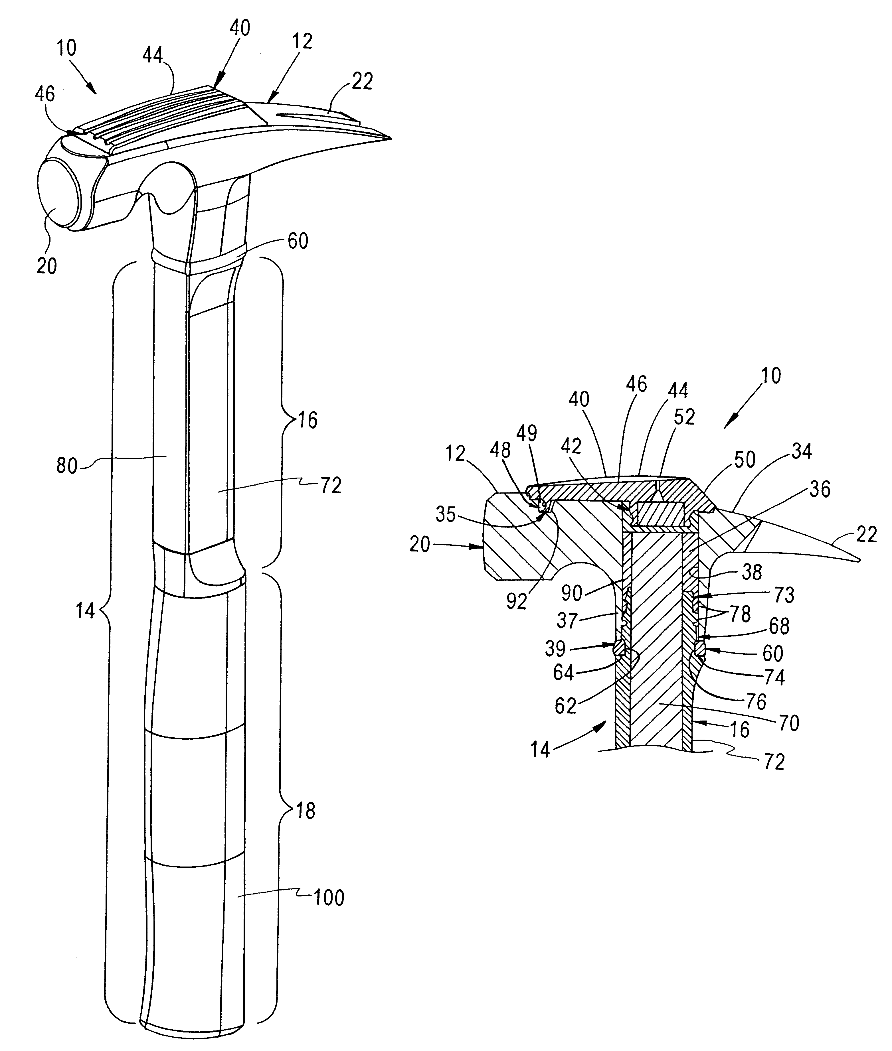
The present invention advantageously provides a shock absorption system that includes a resilient member positioned between a portion of the head and a portion of the shaft of the tool. The resilient member dampens and absorbs vibration travelling from the head to the shaft and reverberations travelling through the tool. The exemplary embodiment of the shock absorption system further includes a shock-absorbing member having an internal portion positioned within a cavity in the head of the tool and an external portion positioned on an upper surface of the head. The resilient member dampens and absorbs vibration travelling within the head and reverberations travelling through the tool. The exemplary embodiment of the shock absorption system also includes a bonding material filling spaces with the cavity and a channel within the head. The bonding material further dampens and absorbs vibration travelling from the head to the shaft and reverberations travelling through the tool. The exemplary embodiment further includes a handle portion on the shaft that has a soft elastomeric outer coating that provides a comfortable grip to the user and hinders vibration from travelling from the shaft to the hand of the user. The shock absorption system of the present invention advantageously reduces vibrations in the shaft that can cause great discomfort to the user and can be detrimental to the health of the user.

Problems solved by technology

One undesirable result of rigidly mounting the head to the shaft is that any vibration produced when the head strikes an object travels through the head and down the shaft to the hand of a user of the tool.
Such vibrations in the shaft can cause great discomfort to the user and can be detrimental not only to the health of professionals who use striking tools repeatedly for extended periods of time, but also to non-professionals who occasionally uses striking tools for small jobs.

Method used


Image

  • Shock absorption system for a striking tool
  • Shock absorption system for a striking tool
  • Shock absorption system for a striking tool

Examples


Embodiment Construction

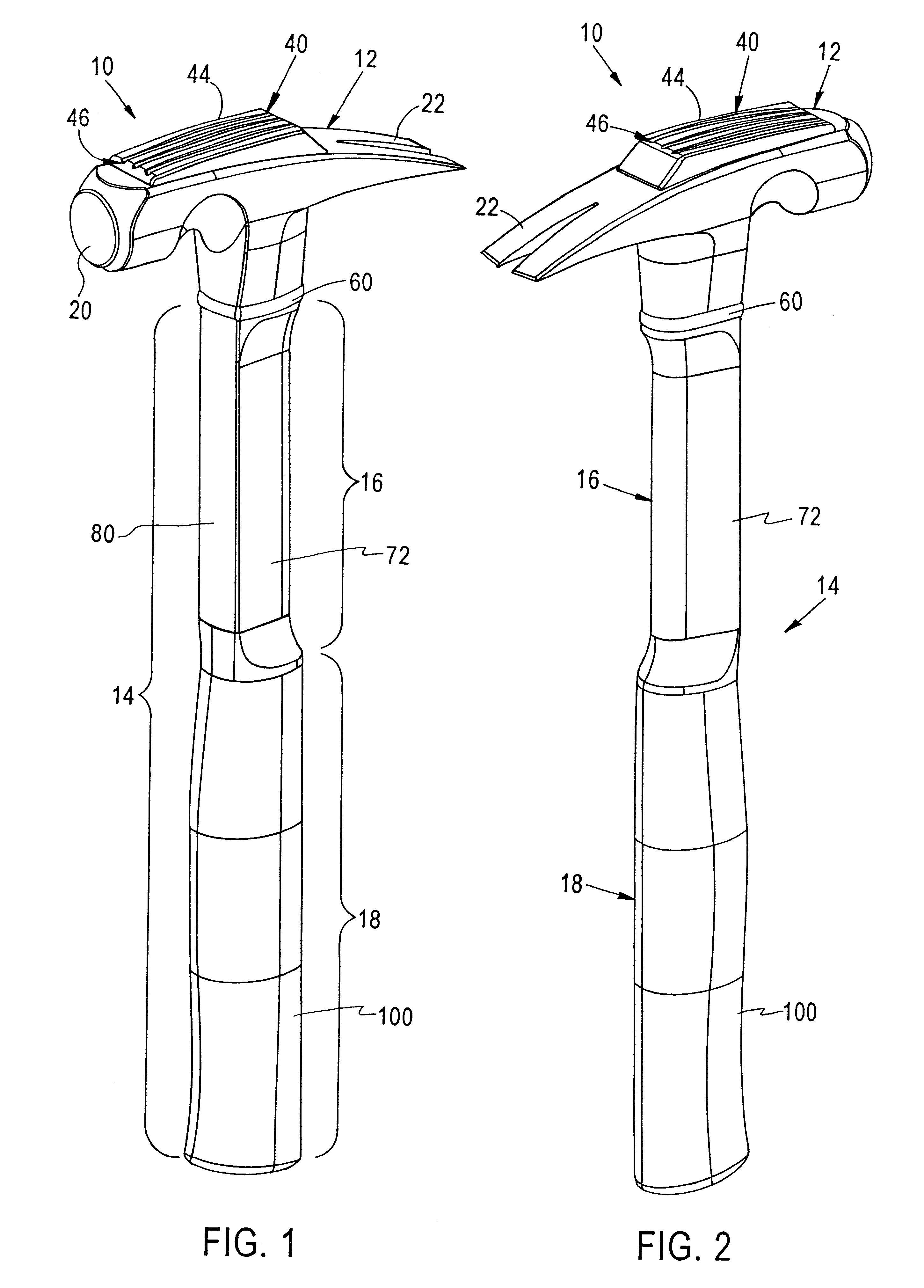
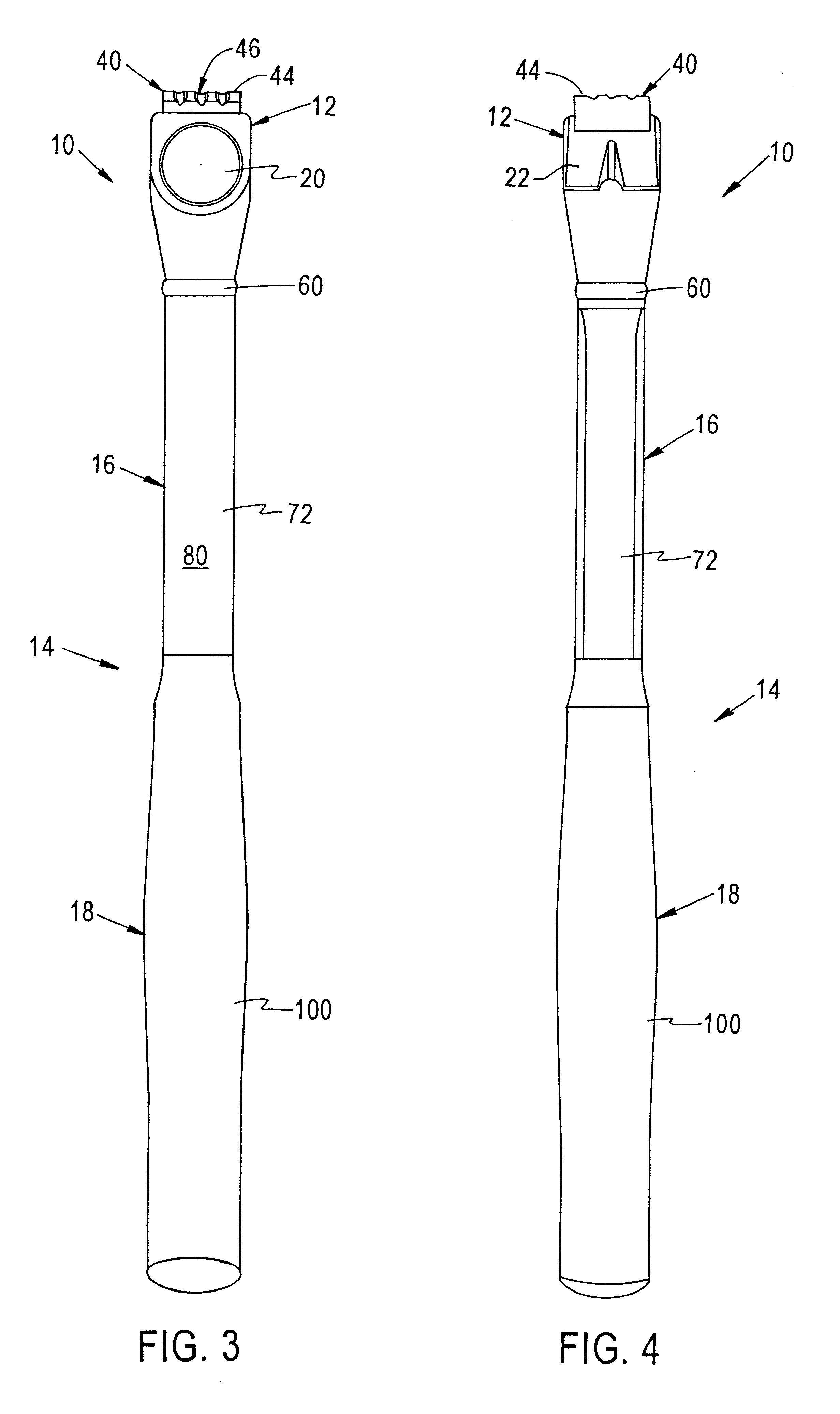
The present invention provides a shock absorption system for a striking tool 10 that reduces the amount of vibration travelling from a head 12 of a striking tool 10 to a shaft 14. The exemplary embodiment of the striking tool 10 as depicted in FIGS. 1-9 is a hammer. The present invention is contemplated to be used with any type of striking tool having a head portion and a shaft portion, for example, sledgehammers, axes, picks, etc., and is not limited to use with hammers.

The striking tool 10 depicted in FIGS. 1-9 includes a head 12 connected to a shaft 14. The shaft 14 of the exemplary embodiment includes a shank portion 16, or neck portion, and a handle portion 18. The shank portion 16 generally extends between the head 12 of the striking tool 10 and the handle portion 18. The head 12 is preferably made of drop-forged high-carbon steel. The shaft 14 includes an inner core 70 made of fiberglass (see FIG. 8) that extends through the shank portion 16 and the handle portion 18. The inn...


PUM


Abstract

A system for absorbing shock including a resilient member positioned between a portion of the head and a portion of the shaft of the tool. The resilient member dampens and absorbs vibration travelling from the head to the shaft and reverberations travelling through the tool. The system also includes a shock-absorbing member having an internal portion positioned within a cavity in the head of the tool and an external portion positioned on an upper surface of the head that dampens and absorbs vibration travelling within the head and reverberations travelling through the tool. The system further includes a bonding material filling spaces with the cavity and a channel within the head that further dampens and absorbs vibration travelling from the head to the shaft and reverberations travelling through the tool. The system includes a handle portion that has a soft elastomeric outer coating that provides a comfortable grip to the user and hinders vibration from travelling from the shaft to the hand of the user.

Description

FIELD OF THE INVENTIONThe present invention relates to hand tools, and in particular, to a shock absorption system for a striking tool having a head connected to a shaft.BACKGROUND OF THE INVENTIONConventional striking tool, such as hammers, axes, sledgehammers, picks, etc., generally include a head portion mounted to one end of a shaft. Typically, the head portion is rigidly mounted to the shaft so that the force exerted on the striking tool by the user is efficiently transmitted through the shaft to the head of the tool. By rigidly attaching the head to the shaft, the force is transmitted through the shaft and to the head so that the contact surface of the head strikes an object with full force. Additionally, the head is typically rigidly attached to the shaft in order to ensure that the head remains fixed to the shaft after repeated striking of the tool on various hard objects.While rigid attachment of the head of a striking tool to the shaft provides for an efficient transfer of...

Claims


Application Information

Patent Timeline
Patent Type & Authority Patents(United States)
IPC IPC(8): B25D1/12B25D1/00
CPCB25D1/12
Inventor LAMOND, DONALD R.HEINZELMAN, BERT D.CLAYPOOL, CHRISTOPHERCORREA, JOSE L.FRENCH, DAVID L.
Owner HELEN OF TROY LIMITED
Learn More