Versatile threaded construction stake usable to anchor and/or support construction forms, including concrete slab foundation forming devices

a construction stake and thread technology, applied in the direction of threaded fasteners, screws, ways, etc., can solve the problems of limited commercial success of contemporary proprietary systems which form concrete slabs on grades, inflexible, and high cost of proprietary systems

Inactive Publication Date: 2002-04-09
BUTLER MICHAEL G
View PDF17 Cites 30 Cited by
  • Summary
  • Abstract
  • Description
  • Claims
  • Application Information

AI Technical Summary

Benefits of technology

An important component of foundation accuracy is easy adjustment of location of foundation forms, so that needed adjustments are made rather than ignored. For custom built structures, provision for easy adjustment of foundation forms is significant. This is because, compared to repetitive construction, relatively far more labor tends to be expended on the custom geometry definition. So, the ability to have adjustment after forms are initially set up, provides a big labor savings for even one unit. It is best if all the foundation form support locations can be adjusted simultaneously. This way an entire lightweight forming unit, which is internally collocating, can be assembled whole, floating on supports, before being committed to the exact permanent placement.
Accordingly, the construction form is conveniently, easily, quickly, accurately, and precisely spatially located and held above the earth. When a pourable construction material is poured into the construction form a slab on grade foundation is created. Each of the construction form, the vertical and inclined stakes, the bent-planar-elements, and the first and second assemblies may all be removed from the foundation of hardened pourable construction material, re-sited, and reused.

Problems solved by technology

While much prior art can be found in the field of slab foundations and related concrete work, the commercial success of contemporary proprietary systems which form a concrete-slab-on grade is limited.
The primary reasons for this are that the proprietary systems tend to be expensive, contrived, and inflexible.
Furthermore, forming a concrete slab on a prepared building pad is not a significant engineering feat, and so is generally endeavored with simple boards and stakes.
The board and stake concept offers design flexibility, but it does have significant drawbacks.
These drawbacks include: wasted labor to define and check geometry, poor accuracy of surfaces and embedded hardware, difficulty in adjusting form locations after stakes are set, and inconsistent repeatability for multiple units.
Back injury, caused by pulling a conventional stake out of the ground, is a common complaint in the foundation business.
Poor foundation accuracy is always a concern, and it has a more consequential negative affect on the framing process for a structure of light gage metal members.
For a long run of perimeter form this results in frequent potential segmental kinks.
Conforming to custom dimension and design requires the cutting up of relatively expensive lengths of form.
Each supporting assemblage is subject to unwanted lateral movement due to the fact that the each of the supporting stake pairs are required to be essentially parallel for vertical adjustment of the yoke, which attaches to them above the forms.
Stakes in loose soils simply do not hold up to this kind of side cantilever loading.
Even bending of the stakes can be enough of a problem, given the relatively high point of attachment.
Each of these assemblages is heavy, clumsy, relatively expensive, and an obstruction to the concrete work, especially for slab-on-grade foundations.
There are too many parts to buy, clean, and maintain.
The rod supports offer little resistance to uplift from the buoyant forces of concrete placement, because they do not have threads capable of threading into earth, and so are not used in that manner.
It is generally understood that foundation construction includes performing redundant efforts at determining geometry, having a difficult time making geometrical adjustments, and then getting complaints about accuracy from the people building the structure atop anyway.
This is because, compared to repetitive construction, relatively far more labor tends to be expended on the custom geometry definition.

Method used


Image

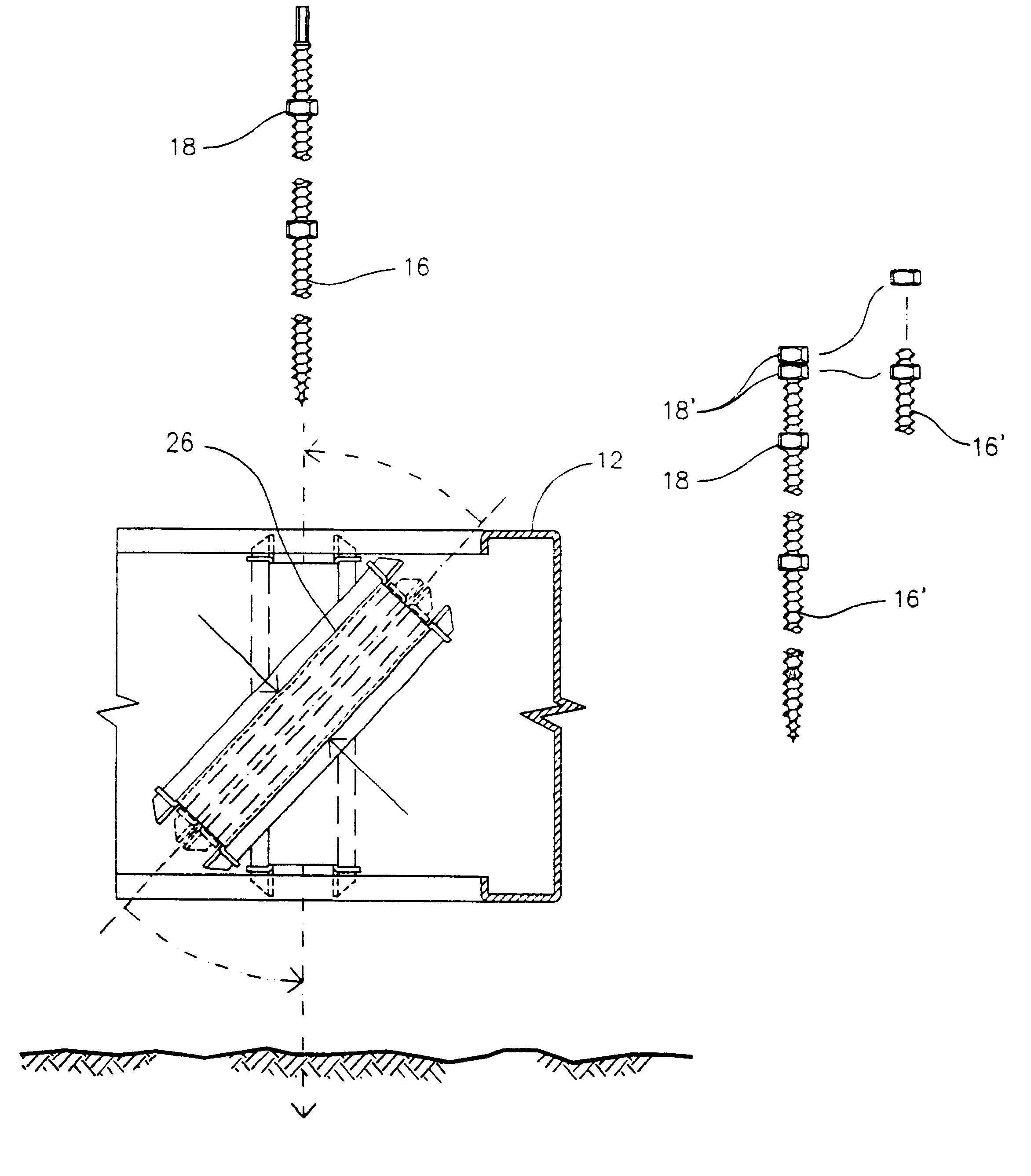
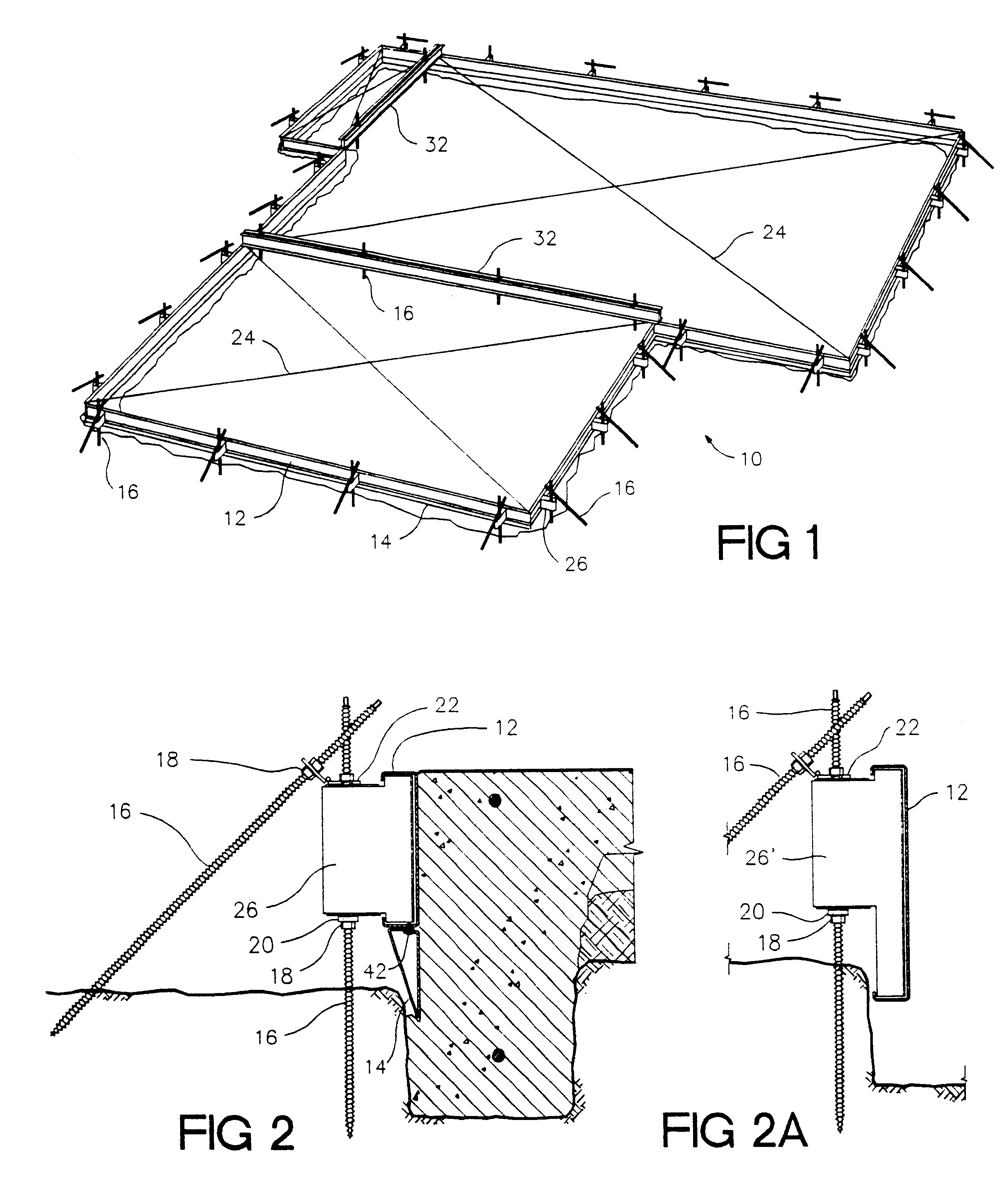
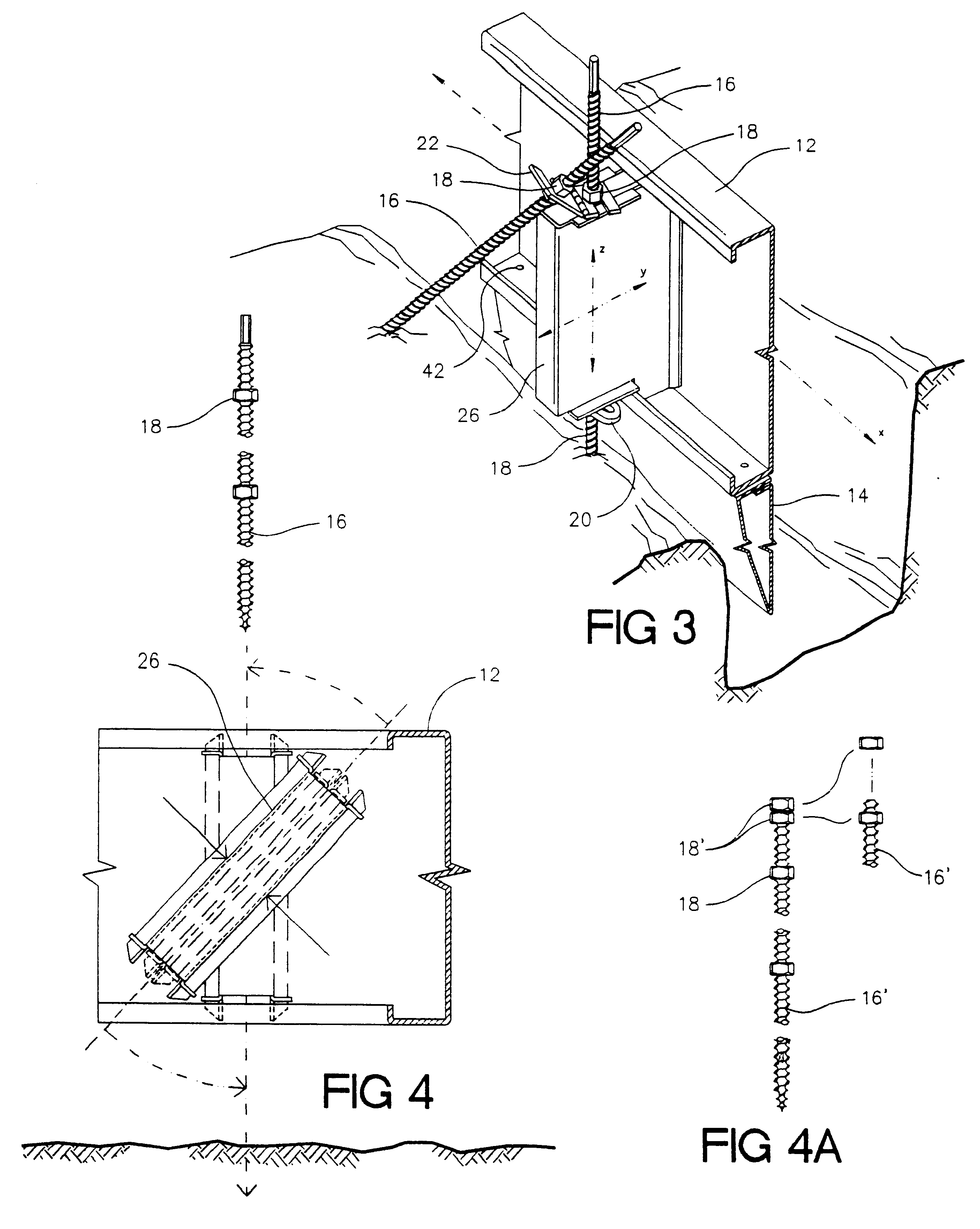
  • Versatile threaded construction stake usable to anchor and/or support construction forms, including concrete slab foundation forming devices
  • Versatile threaded construction stake usable to anchor and/or support construction forms, including concrete slab foundation forming devices
  • Versatile threaded construction stake usable to anchor and/or support construction forms, including concrete slab foundation forming devices

Examples


Embodiment Construction

of a Stake for Use in Construction

The present invention is embodied in a stake generally suitable for use in construction of buildings upon the face of the earth. The preferred embodiment of a construction stake of the present invention consists of an elongate threaded metal member having (i) a length between 0.45 meter and 1.8 meter, (ii) a tapered (pointed) first end region that is suitable to penetrate the earth under force of screwing the member into the earth, and (iii) a second end region in the shape of a regular prism.

The prism-shaped second end region is suitable to be engaged and to be rotated, turning the entire elongate threaded member by a rotating tool which may be manual but which is most commonly a power tool, normally of the pneumatic impact wrench or electric drill type. Particularly by use of a power torquing tool the threaded stakes may be easily driven and strongly set into even the hardest earth. (The stakes are not for use in solid rock, but may easily bypass ...


PUM


Abstract

A stake suitable for use in construction is formed from an elongate threaded metal member, typically of length between 0.45 meter and 1.8 meter, having two ends. A first end region, tapered to a sharp point over typically 3 centimeters, is suitable to be plunged into earth. A middle region has threads that are both deeply cut, typically at a ratio of root diameter to outside diameter less than 0.80, and steeply inclined, typically at least 1 in 20. A second end region has a feature in the shape of a regular prism suitable to be engaged by a torquing tool for rotation of the entire stake. The second end region feature may be a prism of regular cross section, normally a hexagonal prism, of a diameter everywhere less than the minor diameter of the middle region's threads. The second end region feature is preferably (i) a continuation of the middle region's threads in combination with (ii) several, normally two, nuts of 9 mm nominal internal diameter threaded onto the feature and tightly jammed together. The stake is readily screwed into and extracted even from even hard earth by forcible rotation with power tools. The threaded stake readily mounts devices and fixtures, and is particularly useful as part of an assemblage for forming monolithic concrete slab-on-grade foundations in situ.

Description

1. Field of the InventionThe present invention generally concerns improvements to stakes used in construction to temporarily hold things, such as construction forms, in position upon the surface of the earth. The stakes of the present invention will be seen to be particularly, although not exclusively, useful in the practice of a patented method of constructing a monolithic in-situ concrete slab foundation and in related concrete work.The construction stakes of the present invention are particularly useful as part of a construction form system, and in a method of making a slab on grade foundation.2. Description of the Prior ArtWhile much prior art can be found in the field of slab foundations and related concrete work, the commercial success of contemporary proprietary systems which form a concrete-slab-on grade is limited. The primary reasons for this are that the proprietary systems tend to be expensive, contrived, and inflexible. Furthermore, forming a concrete slab on a prepared...

Claims


Application Information

Patent Timeline
Patent Type & Authority Patents(United States)
IPC IPC(8): E04G13/00E02D27/00E04B5/10E04B5/14
CPCE02D27/00E04G13/00E04B5/14E04B5/10E02D2220/00
Inventor BUTLER, MICHAEL G.
Owner BUTLER MICHAEL G
Why Eureka
Try Eureka